Gas Lighting. Part 2
Description
This section is from the book "The Engineer's And Mechanic's Encyclopaedia", by Luke Hebert. Also available from Amazon: Engineer's And Mechanic's Encyclopaedia.
Gas Lighting. Part 2
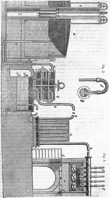
Various arrangements have been employed for this purpose; that shown in the engraving, and which we believe to be generally preferred, is the invention of Mr. Perks, and consists of a close vessel k divided into compartments l l, each communicating with the adjacent one by parallel rows of bent pipes m m, which are surrounded by water contained in the tank n, erected upon the top of k. The gas entering the condenser by the pipe h passes successively through the several rows of bent pipes until it arrives at the exit pipe o, which conveys it to the purifier; by which prolonged contact with a great extent of cooling surface, the tar and ammoniacal liquor become condensed, and fall to the bottom of the compartments l l, and from them are conveyed to the tar vessel p, in which the tar, from its greater specific gravity, occupies the lower portion, and is drawn off by the lower cock, whilst the ammonia, which lies above it, is drawn off by the upper cock; q represents the most approved construction for a purifier when cream of lime is the material by which the carburetted hydrogen is freed from the sulphuretted hydrogen and carbonic acid, with which it is still contaminated after leaving the condenser.
In this arrangement of the purifying vessels, three cylindrical vessels r r r are placed one over another, and from the top of each descends a smaller cylinder s s s, which does not reach the bottom of the larger cylinder, and which has attached to its lower end a broad flange or shelf. The larger cylinders are filled with cream of lime to about one-half their depth, which is kept in constant agitation by broad vanes t t attached to the spindle «, passing through stuffing boxes in the several cylinders. The gas entering the lower small cylinder by the pipe o depresses the liquid therein below the shelf, and then rises up through the fluid into the upper part of the outer cylinder; from whence it is conveyed by the bent pipe v to the second interior cylinder, and from it, in a similar manner, to the third, from which it escapes, as before described, to the outer cylinder, and from thence passes by the pipe to to the gasholder, or gasometer x, as it is commonly termed. The gasholder consists of a large outer cylindrical cast-iron vessel or trunk y, nearly filled with water, in which is inverted another cylinder z of sheet iron, a few inches less in diameter, and open at the bottom; the inner is usually suspended by a chain passing over pulleys, and having counterbalance weights attached to them, so as to allow the vessel to rise easily by the upward pressure of the gas upon its entering.
For the purpose of suspending the inner vessel, a heavy frame, or bridge, was formerly erected over the whole; but a much superior method is now generally employed; in the centre of the vessel z is a tube of about three feet diameter, through which rises a cast-iron pillar 2 to a plate, on the top of which are fixed the balance wheels, the weights 3 3 rising and falling within the pillar. From the gasholder the gas is conveyed by the eduction pipe to the street mains, and from there, or from the various service pipes branching from them, it is conveyed, by small wrought pipes, to the street or private lamps. In order to regulate the flow of gas into the main, at the junction of it with the eduction pipe is placed a regulating valve, and from the main is supplied a lamp kept constantly burning, whilst an attendant, by partially opening or closing the valve, maintains the flame of the lamp at the proper height.
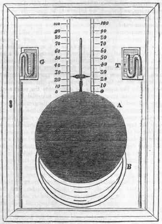
The engraving on the following page represents an improved description of regulating valve, which has been introduced at the Bath Gas Works by Mr. Eastwick, the engineer of that establishment. The valve consists of a circular plate of metal, nine inches in diameter, sliding over the mouth of the main pipe in a chamber; the face of the index is a representation of the valve itself, so made in order that the superintendent may know the precise position of the valve at any time. The disc A is a thin plate of metal attached to a rod coming up from the valve behind the index frame, in which there is a slit for the pin, which carries the index, to pass. The portion of the circle B, which is uncovered by the disc, represents the aperture or gasway into the main pipe. G is a pressure gauge connected with the main on the gasometer side of the valve, and T another pressure gauge, also connected with the main on the town side; there is a burner supplied from the town side of the valve placed before the eye of the person who adjusts the valve.
From repeated inspection of the town lights at all hours of the night, as well as of the burner before the index, the requisite pressure is known and regulated; as the night advances, the valve is lowered more and more, and in the morning (when the lamps ought to be all out) it is depressed to one-tenth of an inch, that being sufficient to cause the exit of the gas in the lowest situations.
The opposite engraving exhibits a new construction of a retort and of a purifying vessel, for which Mr. Hobbins, of Walsal, in Staffordshire, obtained a patent. The objects sought by these new arrangements are, first, an increased facility of charging and discharging the retort without the necessity of luting the joints; and a more rapid decomposition of the coal, by spreading it in a thin stratum equally over the bottom of the retort; and the subsequent purification of the gas, without employing mechanical labour to produce a constant agitation with the lime or other purifying materials. Fig. 1 shows a longitudinal section of a retort, supposed to be placed in a furnace occupying the space between the dotted lines a a; the two ends of the retort are flanged on to the body, and, projecting beyond the brickwork, are removed from the influence of the fire; b and c are two scrapers, with long rods attached to them, which pass through the flanged ends of the retorts, and have cross handles at their extremities.
Continue to:
My Books

