Coil Resistance
Description
This section is from the book "American Library Edition Of Workshop Receipts", by Ernest Spon. Also available from Amazon: American Library Edition Of Workshop Receipts.
Coil Resistance
These consist of coils of wire (German silver or silver - iridium alloy), wound with great care, and of a length to have a resistance of a definite number of ohms. ~ The following instructions for making a set of resistance coils, simple yet reliable, are easily within the reach of any one possessing the few requisite tools. The coils themselves consist of wooden frames (preferably oak), as shown in Fig. 67: a b are 6 in. long, £ in. deep, and rather over 1/4 in. thick; joining them are c d, also of oak, 1/2 in. deep, and rather thinner than a 6, so that they do not come up flush with e f. The tops of a & are grooved, as shown at e f; and at intervals (varying with the size of wire used) are cut notches as shown along a, for the wire to be wound into. If the wires are not larger than 24 or 26 BWG, they may be about 1/8 in. apart. The number of frames is regulated by the number of ohms resistance required to be made up. Upon the frames is wound uninsulated German silver wire, such as may be bought at any metal warehouse. One end is fixed by a screw to a point on c, and winding is commenced, keeping the wire tight, and taking care that it goes to the bottom of the notches cut for it.
When the coils are not likely to be subjected to very powerful currents, No. 28 wire may be commenced with for the smaller resistances, gradually progressing to No. 40 as the resistances increase. When the frames are wound, they are soaked in hot paraffin wax till thoroughly saturated, and the excess is drained off. The next step is to give the coils their true value, according to some available standard. For this is required a simple form of Wheatstone bridge, such as that shown in Fig. 68, and made in the following way: - On a board about 5 ft. long fix a piece of wood about £ in. thick at each end. From the tops of these pieces of wood tightly stretch a piece of German silver wire, and firmly fix it by screws. To 2 points x y near the ends of the German silver wire, solder 2 stout copper wires, leading to 2 binding - screws g h; at i, between them, is another screw. Make 2 clips of stout brass, as shown in elevation and section in Fig. 69; to one of these solder any piece of copper wire, and to the other a stout piece. Place the clip with the thin wire so that it clips the wire x y at any point; let the wire connected with it go to one terminal of an astatic galvanometer, whilst the other terminal of the galvanometer is connected with i.
Let the standard, which may be a piece of wire having a resistance of 1 ohm, be placed between g i, and to h connect the end of the wire on one of the coils just wound. Connect a battery to xy, about 6 Daniel1 cells, though less may do. Supposing it is wished to find what point of the wire on the coils gives 5 ohms: divide the wire xy into 6 parts, and set the clip so that 5 parts are on one side and 1 on the other; then xk : ky : : 1: 5, and the 1 ohm standard is between g and i. Now, having h connected to one end of a coil, connect the end of the stout wire on the other clip to i, and put the clip on different points of the wire wound on the coil till no deflection is got on the galvanometer: this point shows the ends of the 5 ohms, and to it a stout coppet wire is soldered. Similar trials, altering the ratio of xk to ky, will enable any number of ohms' resistance to be accurately marked out. This done, a box is made rather larger than the frames of the coils, and into it the coils are put, first fixing pieces of cork at the corners, so that no contact takes place between the coils.
On the top of the box, as shown at a, Fig. 70, is placed a piece of stout brass, 1/2 in. by J in.; holes are bored at intervals of about 1 in., made tapering with a reamer, and fitted with tapering brass plugs. Binding - screws are fixed at ab; underneath, between every 2 holes, a small hole is bored, and a short piece of wire is screwed in and fitted with a brass nut and washer; these serve both to bolt down the piece of brass and for fixing the resistance coil wire to. Finally, across the centre of each hole, the brass is sawn right through. Fig. 71 shows a section through the plug a, piece of brass b, top of the box c, the pieces of wire d screwed into b, the nut e and washer f, the wire g being clipped between them. Between each pair of brass pieces is clipped some resistance: when all the plngs are in, the current will go from ab (Fig. 70) round by the thick brass at the top; if a plug is drawn, the current has to pass through the resistance that connects the 2 brass pieces thus left without a plug.
It is convenient to have plugs putting in the following resistances:- 1, 2, 2, 5, 10, 10, 20, 50, 100, 100, 200, 500, thus giving any integer between 1 and 1000.
Fig. 67.
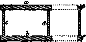
Fig. 68

Fig. 69.

Fig. 70.

Fig. 71.

Continue to:
My Books

