


Collection Chambers And Absorption Apparatus
Description
This section is from the book "Human Vitality And Efficiency Under Prolonged Restricted Diet", by Francis G.BENEDICT, Walter R. Miles, Paul Roth, And H. Monmouth Smith. Also available from Amazon: Human Vitality and Efficiency Under Prolonged Restricted Diet.
Collection Chambers And Absorption Apparatus
The collection chambers and absorption apparatus, as shown in figure 8, are mounted upon a substantial oak table which is provided with a lower shelf. At the extreme right on the shelf is the rotary air-impeller, a, directly connected with an electric motor, t. This discharges the air taken from the respiration chamber into a large copper wind chest, A, shown in detail in figure 9. In the top of this wind chest are three openings. At the extreme right there is an opening, B, figure 9, provided with a water seal into which caps of various sizes can be set. The other two openings, each of 10 mm., lead directly into the center of the bottom of two cylindrical copper cans, C1 and C2. These openings were drilled in disks at the same time and hence are of exactly the same size, which was subsequently proved by most careful calipering. Each disk is attached with a threaded collar to a pipe in the top of the wind chest. Between the 10-mm. disks and this pipe are placed rubber gaskets, which insure tight closure. The details of this installation are given in figure 10, in which a is the brass disk with a 10-mm. orifice, 6 the collar, c the brass pipe soldered to the top of the wind chest, and d the rubber gasket. To attach the cans C1 or C2 to the top of the wind chest and secure an air-tight closure, a rubber gasket, e, is placed between the can and the wind chest and pressure applied by a threaded collar.

Fig. 8. - Side view of collection chambers and absorption apparatus of the group respiration chamber.
Air from the group chamber is delivered into the wind chest A by means of the rotary air-impeller a, driven by the electric motor t. The larger portion of the air is delivered into the open air through a circular opening in B. The remainder passes into the cylindrical copper cans Ci and C2. The air is drawn from C1 through the pipe E by means of the blower F1 driven by the electric motor G. From F1 by means of the tube H the air passes through the sulphuric acid containers J1 and J2, then by the tube K through the 3-way valve V1, soda-lime container L, sulphuric-acid container M, valve Vi, sodium-bicarbonate container N, and finally through the meter O into the open air; an exact duplicate arrangement (see figs. 11 and 12) provides for the removal of air from the cylindrical can C2. b1 and b2 are openings closed by rubber stoppers. P is a delicate petroleum manometer for indicating the pressure in the cans C1 and C2. n1 and n2 are nuts for regulating height of bathing caps on tops of cans C1 and C2. Valves V1 and V2 provide for the deflection of air from C1 into another set of absorbers like L and M. R, hand hole to wind chest A.
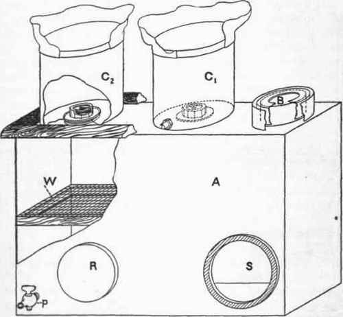
Fig. 9. - Detail of wind chest.
A, wind chest; B, opening to outside, C1, C2, cylindrical copper cans from which air is drawn by means of two Crowell blowers. R, hand hole; S, opening into wind chest for discharge from rotary air-impeller; W, wire screen; p, petcock for attaching manometer to obtain pressure in wind cheat.
As will be seen from figure 8, each of the copper cans, C1 and C2, is provided with a flexible top consisting of a light weight, pure rubber, lady's bathing cap, which allows considerable flexibility in the volume of the can. Near the bottom of the can C1 is a 3/8-inch pipe (13 mm. inside diameter, see E, figure 8), which connects with the intake side of a Crowell blower, F1. The blower is connected by a belt with an electric motor, G. The air discharged by the Crowell blower passes through the pipe, H, and is conducted through two Williams bottles, J1 and J2, containing sulphuric acid, in which the air is thoroughly dried. It then passes through a short length of hose, K, to a header on top of the table provided with a 3-way valve, V\, by means of which the air may be deflected through a soda-lime can, L, and its accompanying Williams bottle, M. The soda-lime in L removes the carbon dioxide from the previously dried air-current and the sulphuric acid in M removes the water vapor imparted to the dry air-current by the somewhat moist soda-lime. The air, now freed from carbon dioxide and water vapor, enters another 3-way valve, V2, and passes through a can, N, containing sodium bicarbonate which removes slight traces of acid fumes. Thence it passes through a pipe under the table to another header, is delivered directly into an ordinary form of dry gas meter, 0, and is finally discharged into the room.
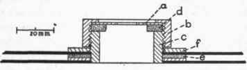
Fig. 10. - Detail of opening between wind cheat (fig. 9) and can C1 or C2. a, brass disk with 10 mm. orifice; b, threaded collar; c, brass tube soldered to top of wind chest; d, rubber gasket; e, rubber gasket; f, threaded collar.
It is thus seen that by this system air coming from the respiration chamber is delivered by a rotary air-impeller into a wind chest and escapes through three openings, the largest being open to the air in the room and regulated in size by disks, and the other two leading into sampling cans with flexible rubber covers. The air delivered to the sampling cans is immediately drawn out through pipes to a Crowell positive blower which forces the air through a series of purifying vessels, i. e., two sulphuric acid bottles for the complete removal of water-vapor, a soda-lime bottle for the removal of carbon dioxide, and finally a sulphuric-acid bottle for the absorption of the water vapor taken up in the passage of the air through the moist soda-lime. After being freed from any trace of acid fumes by passing through a chamber containing sodium bicarbonate, it is delivered into a dry gas meter which gives an accurate reading of the total volume of the sample.
Although the rotary air impeller, a, does not produce positive pressure in the sense that the positive blower, F1 does, it obviously causes a slight increase in the air tension inside the wind chest and the escape of air through the three orifices will be determined in large part by this pressure, which is tested by a manometer attached to the petcock (p), fig. 9, and is more or less roughly proportional to it. Tests have shown that with orifices of the same standard size, the amount of air delivered will vary directly in all cases with the pressure, although it may not necessarily be proportional to the pressure. It is of importance, however, to secure a condition whereby a sample of air delivered through a small orifice can be collected, withdrawn, and the carbon dioxide absorbed, and yet have the discharge through this small orifice under the same physical conditions, so far as pressure and tension are concerned, as the air passing through the large opening, B. In other words, the slight pressure inside the wind chest, due to the rotary air-impeller, renders it particularly necessary to make sure that on the discharge side of the three openings the pressure is always the same, i. e., absolutely atmospheric.
To build a different type of wind chest for each aliquot was impracticable. It was accordingly arranged to make the large opening adjustable, using caps of various sizes to fit over the aperture. By this means the total amount of air leaving the wind chest is reduced and, incidentally, the amount of air discharged into the sampling cans through the 10-mm. openings is slightly modified by the slight increase in pressure inside the wind chest due to the fact that the free discharge is somewhat hindered by the reduction in size of the large aperture.
The maximum pressure inside the wind chest, even when all openings are closed, is, however, so small that relatively large variations in the amount of air leaving the wind chest influence but slightly the actual amount of air discharged into the separate cans. With the rotary air-impeller used and the 10-mm. openings, the amount of air discharged is reasonably constant at about 45 liters per minute, practically independent of the size of the main opening.
Continue to:


My Books

