Plumbing In The American Surety Building. Part I. - Water-Supply Meters, Filter Suction Tank, Pump, Upper And Intermediate Tanks
Description
This section is from the book "American Plumbing Practice", by The Engineering Record. Also available from Amazon: Plumbing: A working manual of American plumbing practice.
Plumbing In The American Surety Building. Part I. - Water-Supply Meters, Filter Suction Tank, Pump, Upper And Intermediate Tanks
(Published In 1896.)
The special conditions and requirements of the plumbing in a modern tall office building involve so many points of difficulty and require such a degree of skill and experience and such good construction in the design and installation that the arrangement and execution of the work, while conforming to the same general principles in different cases, still present diverse features and exhibit special details in each different building, showing how similar requirements have been met and like difficulties overcome by modified plans and varied details. As an example of typical requirements and complete system of plumbing service the work in the American Surety Building, New York, illustrates the general characteristics of a sanitary installation for one of the loftiest com-mercial structures yet erected, and also shows the special details of construction and arrangement adopted to conform it to the exactions of position and severe conditions of high-pressure extended lines, elaborate service, and efficient operation that obtained for this particular building.
This building, on the corner of Broadway and Pine Streets, is about 90x85 feet and 21 stories, or nearly 311 feet in extreme height above the sidewalk. It is intended for about 125 suites of offices, exclusive of all the rooms on four floors, which are occupied by the American Surety Company, and contains a large mechanical plant for the different branches of power, heating and lighting service, etc. The general construction is of the modern fireproof steel-cage system, and the equipment throughout is intended to be of the most improved and complete nature, as designed and approved by the architect, Bruce Price, of New York City.


Mr. E. A. Rogers was the architect's assistant in charge of construction throughout the entire time of building. The plumbing contract was let to James Armstrong for about $45,000, and was executed by him to conform to the general plans and details and comprehensive specifications upon which the estipipe D is connected to two No. 8 Continental filters,* which are provided with the necessary washout and waste and gate valves arranged to have the water pass through the filters or go around them through a by-pass, and so that either or both the filters may be thrown in or out of service at will. The 4-inch delivery pipe E from the filters supplies the 3,ooo-gal-lon suction tank through four 2-inch ball cocks operated by copper floats so as to automatically shut off the supply when the tank, which is essentially an open one, in that it is not designed to receive any pressure, is full. This tank is in a pit under the machine-room floor and it is built of ⅜-inch boiler-iron, 3X3-inch angles and tie-rods, furnished with an iron cover and lock and set in a safe pan with 3-inch waste for drainage. There is a 3 inch valved emptying pipe and a 5-inch galvanized-iron overflow mates and bids were based. The plan, arrangement, and details of operation of the system were designed by Mr. Rogers, and its installation was superintended by him, and from his original data the following description of the characteristic features and operation has been chiefly prepared

PLUMBING IN THE AMERICAN SURETY BUILDING, NEW YORK CITY.
The water supply is taken from the city mains through one 4-inch and two 2-inch pipes which are connected by 4-inch brass unions and gate valve with a 5 inch Westinghouse meter provided with a bypass to enable it to be cut out if necessary without shutting off the supply to the building, as shown in Fig. 1, where valve A in the by-pass is usually kept closed and all the other valves open. By closing valves B and C and opening A the meter can be thrown out of service without interrupting the supply. Beyond the meter the 4-inch delivery • pipe, not shown in Fig. 2, and the pumps are supplied by 5-inch suction pipes laid in iron-covered boxes. All pipes connected to the tank are screwed into riveted iron flanges. The two 14"x7"x10" Worthington steam pumps are supplied, as shown in Fig. 2, both from the suction tank and directly from the street main E, and they are cross-connected and discharge into the tank or fire systems as shown in Fig. 3. Each pump is fitted with a Fisher governor set so as to automatically close the steam valve when the water in the house tanks reaches the upper level required, and to open it as soon as the water falls below that maximum level.
•The arrangement and connections of these filters are conventionally indicated in Pig. 1 to show the operation of the system, but they are not drawn to exact scale or posi-t on.


The normal service of these pumps will be to deliver all the water used in the building (except that taken directly from the mains for basement lines) to the house tanks on the main roof. These tanks supply the intermediate tanks on the eleventh story, and having a connection with the fire line, which would utilize their whole contents for a gravity head for immediate use before the operation of the fire pump. Either pump, when in high-pressure service, must be cut off from the other or house pump and then operates against a check valve that cuts off the roof tank from an upward flow. The pump connection to the intermediate tank is usually closed, but may be opened if it is desired to pump directly into that tank, when the service must be controlled by the electric high and low water gauges, the indexes of which show the heights of water in all tanks on dials in the engine-room.
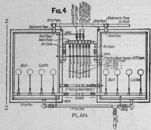
Figure 4 is a plan of the main house tanks, which are situated in a room on the twentieth floor about 350 feet above the level of the pumps, and have a combined capacity of 10,000 gallons, which affords storage estimated to be sufficient, with that of the suction tank, for 24 hours' supply.
Figure 5 is an elevation at Z Z, Fig. 4, showing the vertical pipes, drip pan, special supporting girders, etc. The tanks are filled through eight 2-inch ball cocks that automatically close when the tank is full. Then the continued action of the pumps against the closed valve produces an increased pressure that operates the regulating valve, and shutting off steam stops the pumps until the drawing of water from the tanks opens the ball cocks, relieves the pressure, and steam is again admitted to the pumps. The ball cocks discharge through hush pipes, extending nearly to the bottom of the tanks, and all the delivery pipes from the tanks have controlling valves near the tank, and just below them vent pipes extending up to above the tank so as to facilitate the emptying of the pipe by admitting atmospheric pressure on top of the water inside when the upper valve is closed. All the toilet-rooms, washbasins, and slopsinks above the tenth floor are supplied directly from the upper tanks by the lines taken from the header shown in Figs. 4 and 5, and each of these separate small falling mains has a drip cock at the bottom to empty it into a sink if necessary. As before explained, the 4-inch fire line is direct from the pump to the tanks, and is arranged to operate both under tank pressure and direct high pump pressure. At every story a 3-inch fire valve is set on it, and fitted with 100 feet of 2½ - inch three-ply heavy unlined linen fire hose, tested and guaranteed to a pressure of 300 pounds per square inch, and wound on a swinging bracket reel. The overflow and emptying pipes discharge on the roof, where their contents can be received in the rainwater leaders and their open ends are protected by brass flap valves.
Since the pressure due to the head of the supply from the upper tanks, which reaches 140 pounds maximum, would be excessive for the fixtures in the lower part of the building, all supplies below the eleventh floor are taken from intermediate tanks placed in the tenth and eleventh stories as shown in the elevations, Fig. 6. These tanks are in effect two sections of one tank, and are designed to operate as one, but were constructed separately to enable them to utilize the limited portions of space that could best be assigned to them without obstructing the floors or infringing on rentable room. Portions of upper parts of the lavatories in the tenth and eleventh stories were provided with double ceilings, and in these spaces suspended by iron straps from the steel floor beams above were placed the tanks constructed of the dimensions required to fit their given position. The upper tank is a rectangular open one supplemented by a closed cylindrical one about 13 feet below it, with which it freely connects with a 5-inch equalizing pipe. The normal supply to the tanks is through four 2-inch ball cocks attached to a 4-inch vertical main opening into the bottom of the upper tanks. There is also a 4-inch rising main direct from the steam pumps through which the tanks can be independently filled by opening a valve that is usually kept closed. The supply to the basement drums, whence distribution is made for the lower stories, is through the 4-inch pipe a, valves B, C, and D being open, and valve E being closed. By opening valve E and closing valves B and F, the lower system can be supplied directly from the roof tanks. An overflow is provided for the open tanks, but none is of course needed for the lower closed tank. Each tank has a separate valved connection to the waste pipe, through which its contents may be independently emptied into a basement sink.
Figure 7 is a plan of the open and Fig. 8 is a plan of the closed or auxiliary tank.
Continue to:
My Books

