Drains And Traps - Continued. Part 3
Description
This section is from the book "Plumbing Practice", by J. Wright Clarke. Also available from Amazon: Modern plumbing practice.
Drains And Traps - Continued. Part 3
Some manufacturers have made traps with the inlet-side a few inches higher than the outlet, the bottom of the outlet end representing the water-line. This is an advantage, as the incoming water falls on the top of any floating matter that may be in the trap; but after all this is not effectual, as, if the stream is small and the trap large, eddies are formed, and the trap is not cleansed or the contents entirely displaced. The writer had special instructions to examine a drain that was frequently being stopped up. On seeking for the cause, it was found that originally the drains had not been trapped. It being found necessary that they should be, one had been fixed. This trap, which was supposed to have been of an improved description, was similar to the one mentioned. It had been fixed to the old drains, with the result that it had about 7 inches water seal, and it was choked full of floating matter, the incoming water simply draining away, leaving all solid matter behind. A glance at Figure 153 will explain the cause.

Figure 152.
There are several patent traps in the market, all more or less good, but there are only a few which fulfil their requirements, or that can be called self-cleansing. The best the writer knows are shown in Figures 154, 155, and 156, although there may be others he does not know of. On looking at Figure 154, which is a vertical view, it may be noticed that, although the inlet and outlet ends are made to fit 6-inch pipes, the waste or body of the trap is considerably smaller. The water-fall is 6 inches into this trap. Figure 155 has a water-fall of about 3 inches. Figure 156 shows a sectional elevation, and also a cross-section of the body of another patent trap. The flat top, as shown in small section, is a new departure, but when we come to think that this represents the actual form the water would take in a 6-inch pipe only half filled - ordinary discharges rarely fill a 6-inch pipe so full as this - the inventor can argue that he has reason on his side. And although at first sight one might question the use of the part A, on further consideration it may be found to be a necessity. Supposing that discharges come down the drain to fill it full, or nearly full bore, the water would head up in this part so as to get a greater pressure, and so accelerate its speed through the trap. It may be suggested that the water would splash about this chamber when only small discharges pass down, and that it would be better for the incoming water to fall vertically into the trap as shown by dotted lines.

Figure 153.
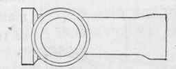
Figure 154. PLAN.
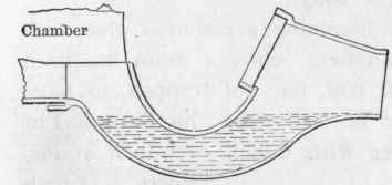
Figure 155. Sectional Elevation.

Figure 156.
Figure 157 is a sectional elevation of a very good drain-syphon, which is patented; the projecting lip at E causing the water to fall vertically on to any floating matter that may be in the trap, instead of trickling down the sides.
There are several other traps which nearly approach those illustrated, but a great many have the fault of being too large in the body.
It is becoming a common plan with sanitary advisers, when a drain has been fairly well laid, but not trapped, to have one inserted, but much smaller in size than the drain. For example, there are several houses with 6-inch or 9-inch diains, where a 4-inch or 6-inch would have been quite large enough. In these cases the smaller-sized common - shaped traps are fixed and connected to the pipes by taper pieces. The incoming pipe is generally fixed as a tapering channel, with a fall of 2, 3, or 4 inches in 2 feet, so that the water runs down with greater speed into the trap.
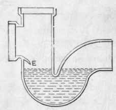
Figure 457.
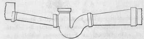
Figure 158.
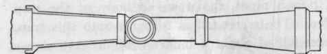
Figure 159.
Figures 158 and 159 are respectively elevation and plan, showing how this is arranged. In one case a 4-inch trap had been fixed in the course of a 9-inch drain. The drain had a very sluggish fall, and was difficult to make a good job of because of the tapering pipes being improperly made. This can be explained better by a sketch, to which I beg to refer the reader - Figure 160 - which is a side elevation, and at A, A the hollow parts, which always retain a quantity of sewage. These pipes, to be properly made, should only be tapered on the one side, and the other should be perfectly straight, as shown in Figure 161, the straight side being placed downward - as mentioned in a previous chapter when writing on bent pipes, and how they should be laid, when, of necessity, they must be used. At the risk of wearying the reader, I must repeat that it is these little pools of decomposing sewage which is the principal cause of the abominable stench generally to be found issuing from ventilation pipes. I have been down a great many public sewers, and I generally find that those which have a continuous stream of flowing sewage are not nearly so offensive as those which have intermittent discharges into them. The result of these kinds of discharges is that very often the solid matters are retained by friction over hollow places, with a corresponding rise beyond them, the liquids simply dribbling away, so that certain matters are only moved by stages, instead of being washed clear away. Sanitarians are becoming more and more aware of the defects of stoneware-pipe drains, and are slowly but surely discarding them in favour of iron ones.
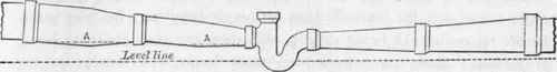
Figure 160.
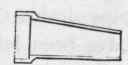
Figure 161.
Continue to:
My Books

