


Effect Of Position Further Considered
Description
This section is from the book "Elementary Principles Carpentry", by Thomas Tredgold. Also available from Amazon: Elementary Principles Of Carpentry.
Effect Of Position Further Considered
19. To take another example: let Fig. 7 represent a frame fixed against a wall, and let the weight be suspended from the point C, where the beams C A and C B join. In this assemblage the beam A C will be stretched, and the beam C B will be compressed; or, in other words, A C will act as a tie and C B as a strut.
To estimate the pressures draw the line C c in the direction in which the weight would move if left at liberty, that is, in a vertical direction; then from a scale of equal parts set off C c equal to the weight in pounds; from c, draw c b parallel to C A, then C b will represent the force pressing on the beam C B; also, c b will represent that tending to stretch C A; these lines being each measured by the scale will give the values of the strains in pounds.
Fig. 1.
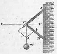
If the position of the beams in Fig. 7 were changed to that shown in Fig. 8, the beam B C would still act as a strut, that is, the weight would have a tendency to compress it: this is evident, because, notwithstanding its inclined position, its place could not be supplied by a rope, which would be the case if it were only stretched.
Fig. 8.

Fig. 9.
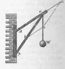
Also, in Fig. 9, A C is in a state of tension, and its place might be supplied by a rope, though it appears from its position to act as a strut. In either of these cases the strains may be estimated as in Fig. 7. As the line representing the weight is the same in each, by comparing the figures it will be seen how much the pressures are increased by altering the position of the beams.
20. The last three figures are each similar to the jib of a crane, but the strain upon the jib of a crane is very different. This difference we will endeavour to explain, and in so doing will point out some principles that ought to be attended to in the construction of jibs.
Let D C E represent the rope by which the weight is raised (Fig. 10) passing over a pulley at C; it is clear that the strain in the direction CD is equal to the strain in the direction C E; but in each of the cases represented in Figs. 7, 8, and 9, the strain was in the direction C E only.
Now if we make C E equal to C D, and draw B E parallel to D C, cutting the line D B in B; then joining B C, we have the direction of a beam that would sustain the forces in the directions D C and E C; and the beam placed in the direction B C would sustain the whole effect of the strains with the least force possible, only requiring a piece A C to steady it.
But when the beam B C is placed at any other position than that found by constructing a parallelogram on the directions of the ropes, the effect of the straining forces will be increased, and will vary according to the position of the sustaining beams. For example, let the beam B C be removed to the position shown by the dotted lines B1 C. Then both A C and B1 C will be in a state of compression. Let the vertical C a represent the weight W, then C b will represent the force in the direction of the beam in the position C B1; and b c that compressing the beam A C, from which the equivalents of these forces in pounds or other weights may be ascertained.
Again, suppose the beam B C to be removed to the position shown by the dotted lines B1 C, instead of B1 C, then it would be compressed, and the strain nearly doubled, while the beam A C would be in a state of tension under a considerable strain. This is the most defective form for a crane jib; yet it is that which is most commonly used. When C a represents the weight W, C e represents the pressure on the beam B2 C; and c e the tension on the beam A C; and being compared with the same line to represent the weight, in each case we see how devoid of principle are the usual methods of construction and how obvious the means of improvement.
Fig. 10.

21. The beam B C in the jib of a crane is called the spur, and the position, so that it shall be the best adapted for the purpose, appears to be a little below the diagonal of a parallelogram, constructed on the directions of the ropes. This diagonal may be found as follows: - Let DP be the shaft (Fig. 11) and DC, CE, the directions of the ropes for raising the weights. Make C A equal to C G, and draw B G parallel to A C, and A B parallel to C G; then join C B and it is the diagonal required. Then, to place the foot of the spur a little lower than the point F, where the diagonal cuts the line of the shaft, causes both the spur and head-piece to be compressed, and produces the strongest arrangement, and one that will move more steadily than any other. It is scarcely necessary to state that in all these cases the beams have been supposed to bo capable of motion at the joints or points of connection; as the firmness that can be given at the joints is so very small in heavy framing that its effect, in all cases where calculation is necessary, may be left out of the question. The methods of connecting or joining framing will be considered in a separate section.
Fig. 11.

Continue to:


My Books

