


Scaffolds, Staging, And Gantries. Continued
Description
This section is from the book "Elementary Principles Carpentry", by Thomas Tredgold. Also available from Amazon: Elementary Principles Of Carpentry.
Scaffolds, Staging, And Gantries. Continued
285. In the foregoing description the staging is supposed to be in one tier only; but in buildings which have to be carried to a great height the staging will require to be raised accordingly. This is usually accomplished by placing a beam of timber across the head of each standard, and projecting some 9 or 10 feet beyond it at right angles to the direction of the runners on which it is made to rest, as 11, Fig. 1, Plate XXXIII. This piece, which is called a " footing piece," serves the same purpose as the foot-block G, Fig. 88; but instead of resting on the ground, it is supported by the struts HH, Fig. 1, Plato XXXIII. These struts are usually in two pieces in order that the struts F F may pass between them.
The standards of the upper tiers should always be placed directly over those of the lower tiers to prevent cross strains on the horizontal timbers. Plate XXXIII., Figs. 1 and 2, show the principle generally adopted for staging of this kind, the upper tier being usually braced by diagonal braces as shown in Fig. 2.
286. The term "gantry " is frequently applied to a structure of timber, such as we have described, but properly a gantry is a staging which carries a traveller only, as that shown by Figs. 87 and 88.
287. Fig. 89 is a transverse section showing the arrangement of the timbers of a staging as used in the construction of bridges and viaducts. The width should be from 10 to 20 feet more than the width of the bridge, and the height of the staging is usually about the same as the springing line of the arch. A line of rails is generally laid on each side to admit of a traveller called a "Wellington," which is similar to that shown by Fig. 88, but with the addition of legs to make it clear the upper portion of the structure over which it passes. By means of this traveller all materials, whatever their weight may be, can be hoisted from the ground with the greatest facility, and deposited in the position they are to occupy in the work. In brick arches or those of rubble stone such a traveller would not be required.
Fig. 89.

In viaducts of great height a staging, as Fig. 89, is also used to support the centering, or in those formed of iron the girders are put together on it. That used in constructing the land tubes of the Britannia Bridge in 1850 was similar in principle to the staging shown by Fig. 89.
When the arches are of considerable span, two or more of the frames shown by Fig. 89 are required for each arch; they are connected by longitudinal timbers or runners, on which the rails are laid strutted, as shown by Fig. 87; or when the distance between the supports is great, wrought iron tie-rods are used as described for purlins, Art. 264.
Where centering has not to be supported,, or in an iron bridge where the girders are not put together in position, a simple gantry, as shown by Plate XXXIII., to carry a traveller is all that is required.
288. The scaffolding used in the erection of comes and roofs of considerable span, as those for large railway stations, is nothing more than a series of standards with longitudinal timbers, and a platform on the top with diagonal braces and struts between the standards, similar to that shown by Fig. 89. The arrangement or plan will of course vary according to the shape and extent of the building. Whole timbers are generally used for both standards, and runners and half-timbers for the struts and braces. The platform is usually formed of planks 3 inches in thickness.
289. Plate XXXIV. shows a sketch of the staging used by the contractors, Messrs. Lee and Sons, in the construction of the Admiralty Pier at Dover, in a depth of water of over 60 feet at high spring-tides. This staging carried a pair of travellers on rails 37 feet 10 inches apart, and also two tramways of 4 feet 10 inches gauge for the trollies which carried the materials to run on, one being on each side of the travellers.
Plate XXXIV
STAGING.
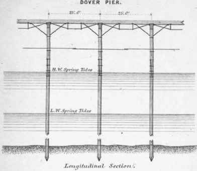


The staging was supported on three rows of piles, from
17 to 20 inches in diameter, and about 90 feet long, but with one splice in each pile above the high-water level. The splices were made good with wrought-iron bands and straps. The piles were shod with iron, and driven into the ground at intervals of 25 feet from centre to centre, and the distance between each row was about 41 feet.
The transverse beams, which were of whole timbers, were in two thicknesses, one above the other, and were secured to the heads of the piles by iron sockets bolted on. Over the transverse beams were laid the runners; those for the traveller rails were formed of two whole balks placed side by side. The tramways were supported by single balks of the same size. A footway about 4 feet 6 inches in the clear was formed in the middle of the stage by planking over the space between the runners of the adjoining traveller ways.
As the staging was liable at times to the wash of a very heavy sea, it was the object of the contractors to construct it so as to offer as little obstruction to the waves as possible, therefore the ties and braces were all made of wrought iron, as shown by the thick black lines in the drawing, and the piles were rounded with the same object. From the great length of the piles under water it was difficult to introduce efficient bracing, consequently to each pile of the outside rows a pair of mooring chains were attached and anchored in the sea, one at a distance of about 490 feet from the foot of the pile, and the other at about 290 feet.
It is rarely that we find a staging erected in such deep water, and it reflects much credit on the skill of the contractors who carried it out.
Continue to:


My Books

