


A Scrap-Basket. Part 7
Description
This section is from the book "Design and Construction in Wood", by William Noyes. Also available from Amazon: Design And Construction In Wood.
A Scrap-Basket. Part 7
VIII b. Making the frame (mitered). If the cleats binding the slats together are fastened, not inside of the slats, but outside, as in Fig. 10, the ends should be mitered.
Mitering is done in the miter-box. If you have a simple wooden one, fasten it in the vise so that it will be rigid, as in Fig. 39. Place one of the cross-cleats in the trough of the miter-box, edge up, and with the back-saw slid into one of the 45° kerfs, cut off the cleat near the end. Do this for all 4 cleats. Now measure accurately the length (7⅞" outside length), put the saw in the other 45° kerf and saw off the other ends. Each cleat will now be of the shape shown in Fig. 40. Test each cleat to see that the end is square with the edge, and that all are of the same length. If not, the ends can be trimmed with a chisel. A convenient way to do this is shown in Fig. 41. Place the cleat, long side down, on bench-hook, the acute angle against cleat of the bench-hook. With chisel pare off sawn mitered surface until it is true. See that all four cleats are alike, 7⅞" long, and with a true 45° miter at each end. In order to test this, set your sliding Tee-bevel at an angle of 45°, as follows: Measure accurately both ways from the corner of a known right angle. Set the head of your sliding Tee-bevel against one edge and set the blade so that it will just touch these two points, as in Fig. 42. The acute angle will be 45°. If you have an accurate iron miter - box, cut a true 45° angle on a piece about 3" wide, and set your. Tee-bevel by this. In case the cross-cleats are mitered, as in Fig. 40, it is necessary to reinforce the joints by means of tin or copper angles. These are made thus: With the scratch awl or a sharp nail draw a center line (diameter) thru a piece of tin

Fig. 39. Miter-box in vise.

Fig. 40. Cross-cleats for scrap-basket.
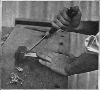
Fig. 41. Trimming a miter.

Fig. 42. Setting a sliding Tee-bevel to an angle of 45°.
2" x2½". On this center line lay off four ⅝" spaces. With the scratch awl and sliding Tee-bevel set at 45°, draw oblique lines both ways from the center line as shown in Fig. 43. With the snips(or a pair of strong scissors) cut out the four braces in the shape shown in Fig. 44. Each one should be just less than 5/16" wide. With a small nailset punch four holes in each piece as shown in Fig. 44. The best way to do this is by placing the tin on a piece of lead, but a piece of hard wood will do. Do not use the top of the bench. Then flatten out the tins. Next nail together the frame by means of the tin braces and the ⅝" flat head nails as shown in Fig. 45. The joints may also be strengthened by driving brads (⅞", No. 18) at ABC, Fig. 45. To do this fasten one piece X firmly in the vise, end up, start the nails A and B in the other piece (Y). Force the end of piece Y a little beyond the end of X, so that when the brad is driven home the outer arrises of the miter will just meet. Do this with all the corners, and lay aside.
IX. Assembling. The parts are now ready to be assembled.
On one long arris of one of the slats, lay out with a sharp pencil and a rule, the position of the slats as in Fig. 46. Using this as a pattern, lay out the same distances on all the upper arrises of the bottom, and on the corresponding arrises of the frame. Next, nail the slats to the bottom piece, as in Fig. 47, driving only one brad (⅞" No. 18) thru each slat, and that one a little away from the center, so as not to interfere with the upholstery nail, which will be driven in later, and yet near enough to the center so that it will be covered by the head of the upholstery nail. The lower end of each slat will be just flush with the lower surface of the bottom.
Continue to:


My Books

