


Taboret. Part 2
Description
This section is from the book "Design and Construction in Wood", by William Noyes. Also available from Amazon: Design And Construction In Wood.
Taboret. Part 2

Fig-. 126. Lay-out of joint of lower stretcher with leg.
¾" from each edge to indicate the centers of the holes for the dowel-pins, with which the joints are to be fastened together. See Fig. 126. Mark center line on the edges of stretchers C at the ends, as at A B, Fig. 127.
To fit the upper stretchers B to the legs, proceed as follows: Draw a fine pencil line across the center of the top ends of the legs and continue this line down both outside and inside of the legs for 2½ " from the top, as in C D E, Fig. 128. On this line on the outside of the leg indicate points A B, ½' and 1½" from the top for centers of holes for the dowel-pins. Mark center lines on the edges of the stretchers B at the ends, C D, as in Fig. 127.
If the legs are to be shaped, as in Fig. 129 the following method may be used:
Clamp two legs side by side and bore a ⅝" hole at the proper point A, in Fig. 130, setting the spur of the bit directly in the crack between the two legs. Bore half-way through, reverse, and finish boring. Re-peat on all the edges. The surplus wood may then be worked out with a saw and spokeshave or small plane.
Next prepare 16 dowel-pins, each 1¾" long and 5/16" diameter. When there are a number of pins to cut off, it saves time to use a miter-box, fastening a stop at the proper distance, (1¾" in this case) from the kerf, and so being able to cut each one off without stopping to measure, Fig. 131.
Next test the size of the dowel-pins in a 5/16" hole bored in a piece of waste wood. The fit should be snug. If the dowel-pins are too large to drive in easily, reduce their size by driving them with a mallet, not a hammer, thru the 5/16" hole in the dowel-plate, Fig. 132.
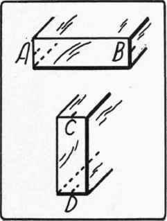
Fig. 127. Center lines AB and CD marked on stretchers.

Fig. 128. Lay-out of joint of upper stretcher with leg-.
Point one end of each pin with a dowel-pointer, (Handwork in Wood, p. 83), to insure their entering the holes readily and round off the other end into a button shape as in Fig. 133. This may be done conveniently with a sharp knife and sandpaper, or better still, of course, on a lathe.
Next the legs and stretchers are assembled as follows: With the hand-drill (Handwork in wood,p.l06,Fig. 187), holding a No. 40 twist-drill which is slightly smaller than the brad to be used (2½", No. 12), bore holes thru all the legs at the points indicated for the dowel-pins, four in each leg. Take especial pains to bore at right angles to the surface, because these holes will afterward determine the direction of the holes for the dowels. Drive the brads (2½", No. 12) into these holes so that their points just come thru. Start the brads (2½", No. 12) into these holes, and placing each leg at its proper place on each stretcher, drive the nails into the stretchers about ¼" and take apart. The dents thus made by the nails in the ends of the stretchers will make it easy to locate them in place when gluing up.
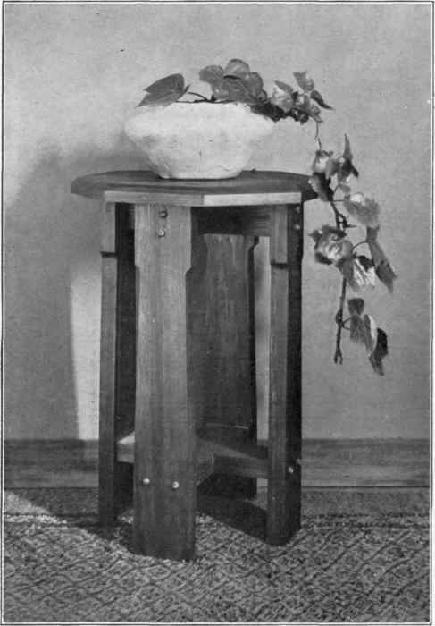
Fig-. 129. Taboret with shaped legs.
Have ready two carpenter's bar clamps, (Handwork in Wood, p. 103), two large (Aldrich's No. 5, 18") handscrews (Handwork in Wood, p. 101), and eight blocks of soft wood, three or four inches long and just large enough to fit between each pair of nails.
If no clamps or handscrews are available, substitutes may be made thus: Cut two boards and two wedges, as in Fig. 134. These improvised clamps can be hooked over the blocks which are placed between the nails, and then the wedges driven in to draw the joints up tight.
Continue to:


My Books

