


Lesson VII. Surface Planing. Continued
Description
This section is from the book "Elementary Woodwork", by George B. Kilbon. Also available from Amazon: Elementary woodwork.
Lesson VII. Surface Planing. Continued
Problem I. Rough Planing
Each pupil takes his rough-ing-plane in hand and follows instructions given by the teacher, who shows how to hold the plane while removing the blade, and then names and explains each of its parts. In removing the blade, strike with a hammer either on the Tear end, A, or on the front portion of the top, B, but never on the front end, C. Re-assemble and adjust the parts.
Take a board, preferably 12 in. wide, though any other width will answer, and saw off for each pupil a piece 8 1/2 in. long. With pencil and straight-edge draw lines on it lengthwise 3 in. apart, as in Fig. 92.

Fig. 92.
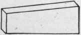
Fig. 93.
Hold this piece in the vise and saw on the lines, dividing it in four pieces, 3 in. rough width. Hold these pieces in the vise successively and rough-plane both edges till saw marks are removed. Two or three strokes of the roughing-plane ought to do this. Be sure that the plane cuts a shaving at every stroke and that it cuts a shaving along the entire length of the work. A common fault with beginners is to omit planing at the rear end, or the end first met by the blade, and commencing when the blade is well on the wood continue to plane the rest of the way, giving the board the tapering shape of Fig. 93. Make sure at the outset that this tendency is overcome.
Problem II. Surface Planing
Take the finishing-plane apart, give names to the several pieces, and explain the province of each. Re-assemble the plane and adjust it thus: Holding it with face uppermost, sight along the face to see if the blade projects. Turn the adjusting-screw, a, in the necessary direction, and move the lever, b, the necessary way to cause the middle portion of the blade's edge to appear in sight while its ends do not, as in the diagram Fig. 94.
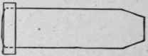
Fig. 94.
Put on the blackboard, or on cardboard to hang permanently on the wall, the two diagrams Fig. 95, to assist pupils in knowing which way to turn adjusting-screws. A is a diagram of the finishing-plane, B of the block-plane. To force the blade of either plane downward, that is, when a thicker shaving is needed, turn the front side of the adjusting-screw in the direction of the arrow. To draw the blade up turn the screw in the opposite direction.

Fig. 95.
A good way for beginners to test the adjustment minutely is to hold the plane in the left hand, face uppermost, and with the right hand draw a small strip of thin board (4 in. X 1 in.
X 1/4 in. will answer) over the edge. A shaving should be cut when drawing such a strip along the middle of the plane's face, as on the dotted line, a, Fig. 96, but not when drawing it near the edge, as on either of the dotted lines b or c.

Fig. 96.
Take one of the pieces which were sawed from Fig. 92, and whose edges have been rough planed, hold it on the top of the bench against the planing pin, and clean one of its sides with the finishing plane, thus : -
Suppose three lines to be drawn lengthwise on the board dividing the side in four sections, as in Fig. 97. First drive the plane so as to have the middle of its blade cut along the middle of section A, then along the middle of section B, then C, and lastly D.
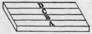
Fig. 97.
It is possible that this effort to plane may demonstrate that some farther slight movements of the screw, a, and lever, b, Fig. 89, are necessary, as the middle line of the shaving ought to come from the middle point of the blade's edge.
The side of the board ought now to be clean. If it is not, repeat with four more sectional shavings when it certainly should be. Do not plane with fury and without thought, or waste the wood, as in Fig. 93.
Clean the opposite side of the board in like manner.
Next true the first side, thus: Provide each pupil with a straight edge which may be of soft wood 16 in. X 2 in. X 3/16 in. with both edges carefully straightened and parallel. Test the work with this straight edge in eight places; viz., three lengthwise tests, one near each edge and one along the middle, as on the dotted lines, Fig. 98; three crosswise tests, one near each end and one across the middle, as on the dotted lines, Fig. 99, and two diagonal tests, as in Fig. 100.

Fig. 98.
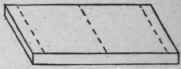
Fig. 99.
Plane wherever these eight tests show the surface to be high, or, in other words, plane the whole surface, following the directions above given for cleaning the surface, with the exception of omitting to plane such points as the above eight tests show to be low. This may be difficult at first, but the difficulty must be mastered. Write pupil's name on the first side when thus trued.
True the opposite side of the board in like manner. If facility has been promptly acquired, the two sides will be parallel, since they were mill planed parallel before the pupil took them. If the pupil has disturbed their parallelism, it must be restored by setting the gauge to the thinnest corner, then gauging from the first side on both edges and both ends and planing to gauge-lines.
Treat all four of the boards in like manner. Rapid workmen will complete the four, and perhaps more, while slower workmen are completing one or two.
When one of the diagonal tests of Fig. 100 shows the board to be high in the middle and the other one shows it to be high in the corners, the surface is said to be "winding," and the process of planing it true is called "taking out the wind." To test long boards for windage, such as two feet and over, apply two straight edges, each 7/8 in. thick X 2 in. wide, one near each end, and sight across the top, as in Fig. 101.

Fig. 100.

Fig. 101.
. Notice that in this problem we have performed two operations, first cleaning the surface and second truing it. In the first operation the plane may be set somewhat coarser than in the second, but in both it should be set as fine as the work to be done will allow. The grinding and oil-stoning must at present be done by the teacher or by some one with skill to do it.
If a board to be planed is wider or narrower than 3 in., more or less than the four sections mentioned in connection with Fig. 97 will be needed. Also the width and consequent number of these sections will be affected by the length of straight portion of the edge of the plane blade.
Continue to:


My Books

