Chapter V. Slide-Rest Work In Metal
Description
This section is from the book "Turning Lathes", by James Lukin. Also available from Amazon: Turning Lathes: A Guide to Turning, Screw Cutting, Metal Spinning and Ornamental Turning.
Chapter V. Slide-Rest Work In Metal
IT will be as well to commence this chapter with a description of one or two Lathes more specially suited for metal-work than those already illustrated, which are chiefly for beginners, and for work of small size. The Lathe of which an engraving is given here, is a very strong one, and is made from 4in. to 6in. centre. It has back gear for slow motion, and can be had with extra hard mandrel and steel collars, but is generally made with gun-metal collars. Price, £13 to £18; weight, 4 ½cwt. The crank shaft runs on friction rollers, and everything is done to prevent the Lathe from working heavily. Such a Lathe as this is powerful enough for metal-work of a tolerably heavy character, and should be fitted with a good strong slide rest. This latter Lathe appliance has gone through many changes of form, but consists mainly of two slides, working at right angles to each other - the lower one moving to and fro across the Lathe bed, the upper moving parallel to it. There is, however, in addition, a quadrant plate, allowing the upper part to swivel round horizontally, so as to adjust the tool for turning cones. Sometimes the upper slide is made to advance or withdraw the tool, and the lower is the one parallel to the Lathe bed; in which case, the whole rest is fitted with a sole plate, or foot, similar to that of a hand rest, and this - which generally slides on a separate cradle, fitted on the Lathe bed, to keep it accurately square to such bed - constitutes a third slide (see Fig. 8). The rest is good for special purposes, but not so well suited for general metal-work, where the greatest rigidity is needed. A small slide-rest of the ordinary make is illustrated at Fig. 9, and is a very useful one for the lighter
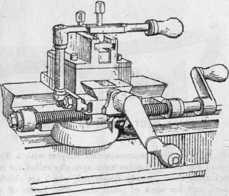
Fig. 8. - W. S. Brown's Slide Rest (Made by Britannia Co.).

Fig. 9. - Small Slide Rest.

Fig. 10.-Strong Compound Slide-rest.
Lathes to 4in. centre already described. Below, and parallel to the top frame, is a tenon, to fit accurately in the bed of the Lathe, to which it is attached by a bolt and hand nut. The tool-holder swivels round to any horizontal position. The quadrant plate and its clamping nut are seen on the right hand, just above the square plate of the lower slide. The next Figure (10) shows a much stronger rest, suitable for turning any work admissible in a Lathe of 5in. or 6in. centres. The tool-holder is also better for heavy work.
With a slide rest it is no longer necessary to cut the metal by short strokes, which produce inequalities demanding to be levelled down by subsequent cuts. The tools traverse steadily along the surface of the work, removing a continuous shaving which is often of a yard or more in length in the case of a self-acting Lathe driven by steam. There is, moreover, not the least strain upon the muscles of the hand, as the tool is rigidly clamped on the upper plate of the slide rest, and all that has to be done by the workman is to turn the handle which causes the traverse. The horizontal angle of the tool is under perfect control by means of the swivelled tool-holder, but all others are evidently fixed and unalterable; front, top, and side rake being determined once for all in grinding the tool. If the chapter on hand turning tools has been carefully studied, it will not be difficult to understand what is required to make a slide-rest tool act perfectly. We have to consider, first, the cutting edges, which must be of such an angle, and such sharpness, as to suit the metal on which they are to be used; secondly, the low clearance angle, as before, which brings the front face or faces at nearly a tangent to the work; and, thirdly, the height of cutting edge, which is always, as a normal rule, to be at the height of the Lathe centres - a rule which it is rarely necessary to alter. The solid tools forged from steel bar are represented here, Fig. 11, from A to G. Some are straight, some bent to right or left, some cranked, and others for inside work. They stand flat on the sole plate of the rest, always lying horizontally. They can be packed up to exact height of centre by parallel slips of iron placed underneath them.
One of the most common tools for roughing-down work is the round end or router, Fig. 11, A; bent to the right or left if the work requires it, B. If well ground and correctly placed, it takes a good bite, and gets over its work rapidly, but does not leave a finished surface. It is, in fact, the gouge of the metal-turner. Another tool for the same purpose is the point or diamond point tool, C. This is a more delicate affair, and it leaves on the work a fine spiral line, which is, in fact, a screw of very fine pitch. These tools are, for iron, bent up somewhat, so as to give an inclined upper face, because the tool cannot be held at a tangent like a wood chisel, and the top face must therefore be ground permanently to a suitable top angle. Then, again, if we look down upon the top of the tool and work, as in the plan view, Fig. 12, S, we shall see that the cut is made by the left side of the curved end as far as the dotted line, supposing, for the sake of distinctness, that a deep cut is taken. The tool is travelling to the left in the direction of the arrow. The part a, therefore, which leads, must have its clearance, or it will rub against the side of the cut; and the point or front must have clearance, or it will rub against the cylinder. To get a good cut out of this tool, the top face or top clearance should be ground in the direction of a b, and not straight down towards the shank. This will give what is called " side rake," rendering the tool sharpest where the line a b touches the work. This is easier to manage if the end is not only bent up, but bent over towards the left, like B of the set just described.
Continue to:
My Books

