


Chapter XV. The Greatorex Patent Milling Machine
Description
This section is from the book "Turning Lathes", by James Lukin. Also available from Amazon: Turning Lathes: A Guide to Turning, Screw Cutting, Metal Spinning and Ornamental Turning.
Chapter XV. The Greatorex Patent Milling Machine
FIX the apparatus on the lathe bed at a convenient distance from the headstock of the lathe, the cutter being already in its place; there must, of course, be a suitable chuck to hold the work. It is convenient to screw out the reducing socket the same size as the bore chuck of the lathe, and so utilise the lathe chucks when desirable. For larger work, it is best to make the chuck to fit the revolving socket (A, Plate XVIII.). Now for simplicity we will suppose we have a hexagon nut to shape up: A tool (Fig. 1,Plate XVII.) is fixed in the drill chuck of the lathe, and the object to be milled screwed to a peg chuck fitting the reducing socket, or the revolving socket (A, Plate XVIII.), as the case may be, the reducing socket or chuck being fastened by the screw-bolt (B); it is then adjusted, by the wheel (C) of the vertical slide, to its requisite height; i.e., the centre of the thickness of the object to be milled should be about the height of the centre of the tool. Bring up the running nut (D) to support the table (E), and fasten the set-screw (F). Next see that the spindle of the spring catch (G) engages with the requisite series of division holes. In this case it will be the series of twenty-four holes, and taking every fourth hole gives the six sides required. The cut should be now set by the wheel (H) of the horizontal slide, and the socket (A) secured by the set-screw (I). Now traverse the work by the handle (K), but be sure not to let the work come on to the cutter until the lathe is working at a fair rate. Set the cut to the gauge by taking equal quantities off two opposite sides of the object to be shaped, and the cut thus set completes the hexagon.


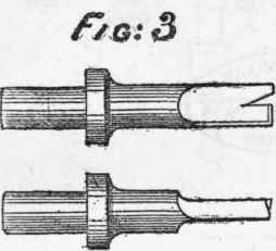
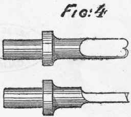
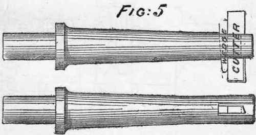
Plate XVII. - TOOLS FOR MILLING MACHINES.

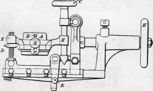
Plate XVIII. - BRITANNIA COMPANY'S MILLING MACHINE.
(Greatorex Patent).


Plate XIX. - BRITANNIA COMPANY'S MILLING MACHINE. (Greatorex Patent).
It will be seen at a glance that drilling is performed by merely substituting a drill for the cutter, and the adjustment obtained by the vertical wheel (C) and the handle (K), the feed being giver by the horizontal wheel (H.)
These two processes represent the principle upon which an endless variety of ornamental work in hard wood or metal can be executed, the cutting edge of the tool being turned to the required pattern; always remembering, if the work is concave, to turn the tool convex; and so on, with reference to mouldings and raised or sunk forms, and with perforations for drilled designs and coronas for lids, and the many methods of ornamenting turned work, bounded only by the taste of the operator.
Before fixing the combination chuck in the socket (A) of the apparatus (Plate XIX.), see that the set-bolt (B) faces the head-stock of the lathe, also that the spring catch is in one of the division holes, and the set-bolt (I) securely tightened; the chuck can now be secured to the socket (A, Plate XVIII.) by the set-bolt (B).
We will now suppose a tap is to be fluted. Place the tap between the centres (C), securing it by the clamps (B), tightening up by the screw (D). A round-nose tool (Fig. 4, Plate XVII.) is used, and the centre line of the tap adjusted to the centre of the tool; or if the tap is a little below the centre of the tool, it gives a more decided cutting edge, thus, J (one size tool will do several sizes of taps). Engage the spring catch (E) with the requisite series of division holes in disc (K), and traverse the tap to the tool by the handle (K, Plate XVIII.) until the flute is the required depth, then set it by the division holes for the next groove, and so on, until the job is completed.
We will now suppose a slot is to be cut in a rod. Place the rod in the V gap, fasten down by the screws G. H; use a tool (Fig. 2, Plate XVII.). It is best to drill a hole at the two extremes of the length of the slot required. Let the centre line of the rod be exactly opposite the centre of the tool; then traverse as in fluting. For key-way cutting, see that the tool is shaped like Fig. 3 (Plate XVIL).
To use the chuck as a vice, remove the clamps (B) by withdrawing the screws, and then objects can be gripped for shaping, drilling, boring, or any other operation within the range of the apparatus.
Fig. 5, Plate XVIL, is a convenient tool for boring; a small cylinder can be gripped in the vice and bored with accuracy by following the lines already given, but it is not well to stop until the cut is through.
The remarks already offered concerning Ornamental Work apply even more forcibly to the use of the combination chuck.
Continue to:


My Books

