Frame Horning And Assembling
Description
This section is from the "The Elements Of Wood Ship Construction" book, by W. H. Curtis. Also see Amazon: The Elements Of Wood Ship Construction.
Frame Horning And Assembling
As soon as the keel has been laid a framing stage is erected over the forward end of the keel, as shown in Figs. 49 and 50. In some yards a stage is built at each end of the keel and two framing crews are operated.
While the framing stage is a temporary structure, it should be strongly built and braced. The decking should not be less than three inches thick. The deck is usually laid over the top of the keel, as this makes it easier to slide the frame off the stage after it has been assembled.
The stage should be large enough to afford ample working room around the largest frames in the vessel. Sufficient blocks, about six to eight inches square and three to four feet in length, are provided to support and even up the first tier of timbers, as shown in Fig. 49. A center board from 12 to 16 inches wide and of the required length is fitted to receive the two horning points O and L. The distance between these points is furnished from the loft. The top of the center-board should be even with the top of the lower tier of the timbers after they have been laid up on the blocks.
In the frame shown in Fig. 49 there are four horning points, and one half-breadth point at the upper deck line. The figure shows the lower tier of a long and short arm floor frame and where the horning points do not land at the butts they are shown scribed on the timbers and numbered. It will be noted that three points on one side and one point on the other side of the frame land away from the butts. This would not necessarily occur in all long and short arm floor frames, but in any event where the horning points do not land at butts they are scribed on the timber and marked with the proper number.
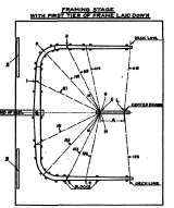
Figure 49. Frame Horning And Building.
Figure 50. Side View With Frame Removed.
HI, H2, H3, and H4 represent horning diagonals, and these may or may not remain in the same relative position. In square frames forward and aft it is sometimes advisable to carry the horning points further up on the frame, but if the horning points are properly marked on the timbers this will not change the system of horning, or cause confusion.
A long square pole called a horning batten is furnished from the loft, and has each of the four sides numbered respectively 1, 2, 3, 4, to indicate the horning diagonal it represents. From the same end of this batten are marked the proper horning distances; that is, on the side numbered 1, the various lengths of H1 from the center O to the outer and upper corner of the lower tier at the first horning point are scribed and each distance marked with the number of the frame for which it is to be used. On the side numbered 2, the various lengths of H2 are scribed and marked in the same manner, and so on with H3 and H4, all being measured from the same end of the batten. A separate batten, called the half-breadth batten, is furnished for the half breadths at the deck and it is scribed and marked in the same manner as the homing batten. Now, with the stage prepared and equipped with center-board, blocks, etc., and with horning and half-breadth battens at hand, the assembling of the frame will proceed.
Assume that the number of the frame to be assembled is 10. The lower tier will be assembled as follows: First the floor is placed upon the blocks approximately in its proper position. Then with the horning batten, using the distance H1 marked for this frame, scribe arcs M-M and N-N across the center board from the horning points No. 1 as centers. Note that one of these centers falls at a butt and has, therefore, not been numbered in the figure. Where the two arcs cross drive a nail. Next, with a fine line, or straight edge, laid against the nail, and on the center-line scribed across the floor, draw the center-line shown on the center-board, measure up from the nail the distance A, which is furnished from the loft, and drive another nail. In practice the fine is not drawn on the center-board, and the distance A is measured along the line or straight edge held in proper position. As soon as it has been found that the arcs will cross on the center-board the floor is dogged fast so that it cannot move, and the arcs and measurements for the two points on the center-board should not be finally taken until the floor has been dogged.
Continue to:
My Books

