Hatch Framing
Description
This section is from the "The Elements Of Wood Ship Construction" book, by W. H. Curtis. Also see Amazon: The Elements Of Wood Ship Construction.
Hatch Framing
Three types of hatch framing have been selected as being the most representative of the many different constructions used.
That shown in Fig. 122, type I, is in use at the present time in large vessels having either no shelf strakes or very light shelf strakes, in either case the beams being fitted with hanging knees. The figure is shown without shelf and with hanging knees spotted under each beam.
It will be noted that the fore and after, or hatch trimmer as it happens to be called on these vessels, is dapped into the hatch beams and connected thereto at each end with a large lodging knee. The half beams are in turn dapped into the hatch trimmer and are connected thereto with flat iron straps turned down over the inside of the trimmer and well fastened with countersunk head bolts into the half beam. These daps should be cut with a standing bevel from the top of the hatch beam, or fore and after (hatch trimmer), and inaddition should have a step or landing worked about halfway down the side of the beam or fore and after, as shown in the figures. The bevel should be such as to carry the dap in on the upper face not to exceed 2 to 2« inches, according to the size of the beam, and the step may be made from « to ¾ inch wide. Not only does this form of dap make the fitting and fastening of the trimmers and half beams easier, but it actually adds to the strength of the connection.
Where fore and afters, or trimmers, are deeper in molding than the hatch beams, they are generally dapped up from below as shown in section C-C, Fig. 122, and the dap is made without bevel. These rules in general apply to all hatch framing.
The various sections below the main figure show the shape of the end and side coamings both for the weather and lower decks. Note that the end coaming is set on the beam and that it can therefore be placed and fastened when the side coamings are fitted. The absence of individual lodging knees at the ends of the hatch and half beams in these vessels is compensated for by fitting diagonal steel straps on the beams before the decking is laid, these straps being set in flush with the tops of the beams and extending from side to side of the ship. At their ends they are riveted to a steel deck stringer plate which in these vessels takes the place of the waterways. A section showing one form of this stringer plate is shown in Fig. 137
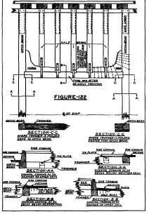
Hatch Framing Type-1.
Type II, Fig. 123, also shows a construction that is now in use in large ships. Here there are heavy shelf strakes under the beam ends in place of hanging knees. The fore and after is dapped into the hatch beams and connected thereto by a small lodging knee, while the half beams are connected to the fore and after in the same manner. Typical arrangements of fastening for these lodging knees are shown.
Another feature of this construction is the continuous stringer, on each side, under the fore and afters, which extends fore and aft at least to the peak bulkheads. This is fitted not only to furnish additional strength in way of the hatches, which is quite essential, but to add to the strength of the ship itself.
Coamings in this type of hatch are generally fitted in the same manner as those shown in Fig. 122.
Type III, Fig. 124, is a construction that is much used where the beams are fitted with hanging knees to the exclusion of all shelves. Here the fore and after is fitted in the usual manner and the half beams have lodging knees at each end. Chocks are shown fitted between the beam ends over the clamps.
These beam chocks are in reality a part of the beam fastening and they are quite commonly fitted to all beams in the ship and not only to those in way of the hatches as the reader might be led to believe through the fact that owing to the limits of the page they are here shown only in way of the hatch framing. Further on in this chapter are details showing these chocks without respect to the hatch framing. Beam chocks are not fitted in ships using the style of hatch framing shown in Fig. 122. They may or may not be used with the type of construction shown in Fig. 123, and are invariably used with the construction shown in Fig. 124.
In way of lodging knees they are extra fastened as shown in the figure. In any event they receive from two to four drift bolts into the clamps, and also have a hardwood treenail set in the joint between beam and chock at each end to assist in locking the beam in place. In some cases the chocks are omitted in way of the lodging knees, the latter then being fitted direct to the frame. Where this is done and the beam spacing is the same as that of the frames with a beam against each frame, the bays must be chocked to provide room for driving sufficient knee fastening.
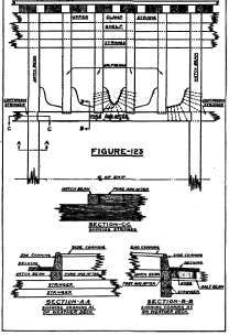
Hatch Framing Type-II.
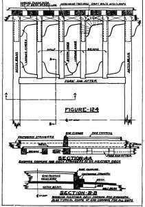
Hatch Framing Type-III.
Continuous stringers are fitted on each side of these hatches on top of the beams and extend fore and aft at least as far as the poop and forecastle bulkheads. The side coamings are quite small and set on top of the larger of the two stringer members. The hatch end coamings set on top of the decking, and are therefore not fitted until after the decking is laid. It will be noted that the decking projects inside of the end coamings, forming a ledge which is later used as a support for the strongbacks.
Continue to:
My Books

