Laying Out Teeth
Description
This section is from the book "Machine Shop Work", by Frederick W. Turner, Oscar E. Perrigo, Howard P. Fairfield. Also available from Amazon: Machine shop work.
Laying Out Teeth
The method of laying out teeth of the first class is shown in Fig. 264. The pitch circle A has its center at B, upon the vertical line BC, From this center the addendum circle D and the dedendum or root circle E are drawn. From the vertical line BC, and to the right and left on the pitch circle A, are laid off the centers of the teeth, and the radial lines 1, 2, 8, 4, 5 drawn. Through a, the point of intersection of the vertical line BC and the pitch circle A, is drawn the arc F, of one-half the radius of the pitch circle. Through the point of intersection b of this arc with the radial line 4-equal to the pitch from the vertical line BC-the base circle G is drawn. To the left of the vertical line BC and on the pitch circle A, is set off one-half the thickness of the tooth-one-fourth the pitch-to the point c. With a radius equal to bc, and from b as a center, the arc d is drawn, representing the face and flank of one side of the center tooth. With the same radius, and with the intersections of the radial lines 1, 2, 3, 4, and 5 with the base circle G, the arcs representing the faces and flanks of the other teeth are drawn. The bottom clearance is equal to one-tenth the thickness of the tooth on the pitch circle; therefore the arcs d are brought down to within this distance of the dedendum or root circle E and completed with a small arc of a radius equal to the clearance. This method is adapted to the teeth of gears of the first class (30 teeth or over), and will be found applicable to gears cut from solid blanks or those with cast teeth, making proper allowances for clearance in the latter case.

Fig. 263. Generation of Involute.

Fig. 264. Laying Out Large Gears.
Gears of less than 30 teeth comprise the other two classes. It is readily seen that as the gears are very much reduced in diameter, the angle at which the teeth of one enter the spaces of the other will require a modification in the form of the teeth.
The method of forming the teeth of gears of the second class is shown in Fig. 265, and follows the method shown in Fig. 264, up to the location of the center for the arc forming the face of the tooth. In this case it is located at the intersection of the tooth curve d with the base circle G; and the flanks of the tooth are radial instead of parallel lines.

Fig. 265. Laying Out Gears of Second Class.
The method of forming the teeth of gears of the third class is shown in Fig. 266. This method proceeds in the same manner as shown in Figs. 264 and 265 as described above, up to the location of the center for the arc forming the face of the tooth. In the first case, this was at the intersection of the arc F with a radial line drawn through the center of the adjacent tooth, and for second-class gears it was at the intersection of the arc F with the flank of the tooth. In this case it is located at the intersection of the arc F with a radial line drawn through the center of the space. The curve d is therefore of relatively shorter radius. Instead of prolonging the curve d to the clearance arc, the flank of the tooth is formed by straight lines // parallel to the vertical line B C and tangent to the curve d. These three methods of describing the forms of involute teeth, for the three classes described, produce curves very closely corresponding to the theoretically correct involute curves, and quite sufficient for all practical purposes for which gears having teeth cut with circular cutters are intended.
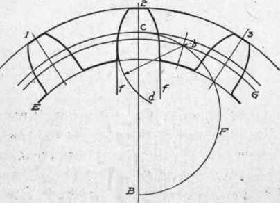
Fig. 266. Laying Out Small Gears.

Fig. 267. Laying Out Teeth of Internal Gear.
Continue to:
My Books

