


Clocks
Description
This section is from the book "Workshop Receipts For Manufacturers And Scientific Amateurs. Supplement Aluminium To Wireless", by The Chemical Publishing Co.. Also available from Amazon: Workshop Receipts For Manufacturers And Scientific Amateurs.
Clocks
An Electrical Clock
A good deal of attention has been given in recent times to the subject of electric horology and a number of electrically-propelled clocks have appeared upon the market. The earliest types of electric clock attempted to re-wind, by electrical means, ordinary weight or spring-driven mechanisms. It was soon realised, however, that this was a needless complication, for the spring or weight mechanism, which absorbed much power, could be entirely dispensed with and the electrical method applied directly. This was found to result in a much more simple clock mechanism, requiring less power to drive it, with consequent reduction in wear and increase in reliability. Although the direct-driven electrical clocks were at first to some extent used for astronomical and scientific purposes on account of their delicacy, it has now been made possible for such clocks, suitably modified, to be applied to ordinary household and commercial time-keeping purposes. We have recently had an opportunity of examining and testing what is probably the most widely-used electrical clock in the world, namely, the Bulle Clock.
The Bulle Clock
Before describing the method of working of this clock an outline of its properties and advantages may profitably be given here. The Bulle Clock, which was invented by Moulin and Favre-Bulle, employs a fixed magnetised bar and a cylindrical pendulum bob consisting of an electro magnet having a central hole to clear the fixed bar magnet. Once every complete swing the solenoid is energised by means of a contact worked by the pendulum movement and a mutual attraction occurs between the solenoid and the fixed bar magnet; this supplies the required impulse to work the clock train. It has been estimated that an ordinary primary cell of the improved Sac Leclanche type has a capacity of about 50 watt hours, and a simple calculation shows that one watt hour is equivalent to 3,600 joules. When the electrical energy of such a cell is converted into mechanical work it is equivalent to the raising of a weight of lib. through a vertical height of about 130,000 feet. It can be shown that this energy is more than 50,000 times the energy stored up in the mainspring of an ordinary watch. Allowing for losses of energy between the cell and the hands of a clock it is evident that the primary cell can, if properly applied, furnish the energy necessary for actuating a clock over very long periods. Indeed the results obtained with the Bulle clock prove that a small cell of a few cubic inches capacity is sufficient to run such a clock for several years without attention, other than the replenishment of the water in the cell, at long intervals. Briefly the Bulle clock dispenses with the ordinary spring mechanism or weights and employs only the fixed bar magnet, a moving solenoid coil and a small compact train of wheels; the latter consists of a ratchet wheel, driving a worm which engages with a worm wheel which drives the minute hand direct. The hour hand is driven through a 60-to-one reduction gear ; this comprises all the mechanism of the clock. An Invar steel pendulum rod is fitted in order to minimise the effects of temperature changes. The complete clock is quite robust in appearance and in actual use. It can be moved about, shaken and treated fairly roughly without damage. It can also be tilted through an appreciable angle from the vertical without affecting its efficient working. Further, if the clock be accidentally stopped, it commences to build up its swing in a very short while, and to work steadily thereafter. Only a very small amount of electrical energy is required to maintain such a clock, so that the battery or cell employed can be quite a small one. Another advantage of this type of clock is that it can be made quite noiseless. Owing to the small magnitude of the working forces the amount of wear on the mechanism is extremelv small.
The principle of the clock can best be understood by reference to Fig. 45. Here we have a special bar magnet which is magnetised in a peculiar manner so that its extremities are south poles and its central portion a north pole. The pendulum bob, as will be seen, consists of an electro-magnet coil or solenoid A, carried by an Invar rod F., which is suspended by silk strips from a fixed horizontal bar. Current is conveyed to the solenoid via contact members D and g, which is arranged in the mechanism of a clock. When the circuit is completed and in the position shown the coil is magnetised in such a way that it has a north pole on the right and a south pole on the left. It is, therefore, attracted to the right due to its repulsion from the left hand and attraction to the right hand side. It should be explained that only one contact is made per double swing, and this is arranged at the centre portion of its swing from left to right. Referring to Fig. 46 the connections to the contact arm F are shown. A pin which is arranged perpendicular to the pendulum rod F, near its upper extremity, alternately makes contact with the pivoting fork F, one side of which is insulated, the other being given a silver contact piece. In this way, only when the pin on the pendulum rod makes contact with the silvered side or prong of the fork is the electrical connection between the battery and the solenoid made and the impulse received. Whilst the pin passes over the insulated portion the circuit is open. Details of these movements are shown in Fig. 47. The shaft containing the pivoting fork piece F carries at its front extremity a spring ratchet R, which engages with the edged teeth on a horizontal wheel immediately to its right as shown at S in Fig. 47. The teeth on this wheel are cut on the upper annular rim ; there is also a second ratchet to hold the wheel when the other ratchet is not operating it. The wheel S drives a worm T, engaging with a worm wheel U, carrying a shaft upon which the minute hand of the clock is mounted. This shaft also carries a small pinion engaging with a large tooth wheel which in turn drives through a similar reduction gear the hour hand. A reduction of sixty to one is effected in these two trains of gearing. In this way both the minute and the hour hands are driven. Referring again to Fig. 47, it will be observed that there is a conducting spring M, which serves to carry the current from the pendulum to the standard which forms the earth return. Other parts of the mechanism are suitably insulated. There is also a regulating screw 2, to enable the clock to be regulated for time. It will also be observed that the whole mechanism is extremely simple, and that there is little to go wrong other than battery. It is necessary, of course, to exclude dust in the case of clocks running for such long periods of time, otherwise excessive wear might conceivably occur. In connection with the electrical contact between the pendulum pin and the fork, it should be mentioned that this is a rubbing contact, and that the current is very small, so that no sparking occurs ; indeed the contact tends to improve with use due to the rubbing action. There is a light tension spring fitted between a point on the Invar rod and the frame so as to limit the amplitude of movement on the pendulum, otherwise this might become too great. None of these clocks at present are fitted with striking mechanism. This would mean more complication and would no doubt increase the cost. The Bulle clock mechanism is fitted into a large number of clock models. We are informed that there are over 110 standard models from which to choose. Many of these are of attractive design, but there appears to be a model for every conceivable purpose in connection with the application of clocks.
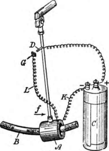
Fig. 45.

Fig. 46.

Fig. 47.
Luminous Clocks And Watch-Hands
Clean the hands very thoroughly, then coat with ordinary photographic bromide emulsion, doing this in a red light, then soak in an ordinary developing solution for 15 minutes or so. Wash thor oughly, and dry well in the dark for 24 hours. Keep in the dark and immerse in a saturated solution of aluminium sulphate, to which has been added a few drops ot saturated solution of sulphate of quinine (to which a few drops of sulphuric acid has been added). This will make the objects phosphorescent at once. Take out and allow to dry slowly. Repeat this soaking in the last mentioned bath every two or three hours, and expose to the light between each soaking.
Clock Troubles
The stoppage of a clock may be due to many causes, some of which are easily discovered and remedied. Observe whether the two hands are together along their length, or whether one has caught on the second hand, or on the inside of the glass front, if so the remedy is obvious, and one hand is either bent, or else is loose at the centre, allowing it to sway about. Observe also whether the clock tick (when restarted) is even, that is not louder on alternate ticks, the remedy is to alter the clock level until the ticks are equal in intensity. Another simple reason for a clock stopping is that the weight-cord is catching somewhere, and so taking the driving weight off the clock. To stop a pendulum clock is simple if the pendulum can be got at and stopped, and a spring driven clock can be stopped by inserting the winding key and turning slightly so as to take and hold the twist of the driving spring. The key is held until the clock movement stops. With most clocks this takes a very short time. To tell whether a mantelpiece clock is level, a steel ball will be found useful, its movement along the mantelpiece will tell in which direction it slopes, and in what direction to pack up the clock base. See Vol. 1, page 337.
Continue to:


My Books

