


Instructions For Operating
Description
This section is from the book "Workshop Receipts For Manufacturers And Scientific Amateurs. Supplement Aluminium To Wireless", by The Chemical Publishing Co.. Also available from Amazon: Workshop Receipts For Manufacturers And Scientific Amateurs.
Instructions For Operating
Opening Doors
Open double doors and release safety bolt of door on reverse side, remove top spool box.
Fitting Top Spool Box
After removal place spool box on top of case, inserting the channel in slot at top and engage studs into slots.
Electric Connection
-Raise flap and attach cord to hook inside top. See that switches are in an "off position. Plug the flex from the house supply into switch. Connect the triple loose flex to the resistance in the following manner :-There are three terminals with red disc, without disc, with green disc; insert the ends of the triple loose flex which are similarly coloured in the corresponding positions. Turn on switch.
Centring Light And Bough Focussing (Fig- 39)
The lamp is adjusted as finely as possible before despatch; if the screen illumination is not even after the masked line has been focussed sharply on the screen, by means of the focussing knob 16, it may be necessary to make certain adjustments to obtain the best results, viz. :-(1) Loosen the two screws 17 and slide the lamphouse 18 backwards and forwards. (2) Loosen the screw 19 holding mirror, and slide backwards and forwards. (3) Loosen knob 20 and raise or lower lamp. All screws should be firmly set after these adjustments have been made.
Placing New Lamp In Position
Remove mirror by loosening screw 19. Slacken screw 21 and remove lamp platform.
Loading Top Spool Box
Detach top spool box, open door, and remove complete spool. The spool will be found to divide. Place reel of film over the large spindle and assemble spool. Lay complete spool of film into the box and thread end of film through the channel, see the direction of the film runs from left to right, close the box and place in position in manner described.
Threading Film (Fig. 39).-Pull through approximately 3 feet of film. Move shutter blade into an upright position. Swing the jockey roller 24 to the left, draw film under front of the same, lay round the sprocket 25 so that the perforation holes engage and thread through roller 26, close roller 24. Open gate by means of pull-out knob 27, and engage on intermittent sprocket 28. Care should be taken to see that the picture opening corresponds with mask. Close gate with thumb, holding film in position. Lift cradle roller 29 and lay film over the sprocket 30, threading the film between jockey roller 31. Lower cradle roller 29.
Special Note
It is most essential that adequate loops in the film should be left at points 32 and 33. Open door of bottom spool box 34 and remove loose side of spool, thread the loose end of film through tunnel 35, bring the film under boss of the spool and engage under clip, replace loose side of spool, seeing that the peg on the spindles engages into the hole at back of spool. It is important that the film should be taut as between the sprocket 30, the channel 35, and the clip on the boss of the lower spool.
Note
The spool in action revolves from left to right.
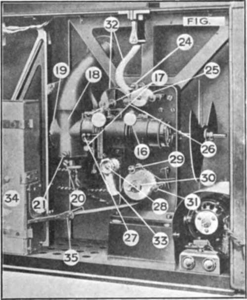
Fig. 39.
Preparing For Projection
See that switch button is up and off. Close and bolt the main doors. Turn on switch which puts motor into action, at the same time giving full power of light on screen. Speed of motor can be regulated by sliding knob.
Fine Focussing And Centring
Focussing is operated by turning knob left or right; centring of picture to the mask is actuated by knob.
Projecting Still Picture
Turn off switch and if shutter obstructs the rays of light the same can be moved by means of milled knob at opposite side of case-the same knob can be used for projecting single consecutive pictures.
When The Film Is Nearly Finished
It is advisable to slow down the motor slightly by regulator to prevent strain on end of film.
When The Picture Is Finished
Open main doors and remove bottom spool box, and allow the safety flap to spring into position.
Replacing Bottom Spool Box
Lift up flap at rear of spool box and slide on to spindle.
Special Note
Use screwdriver provided. Oil at all red points on mechanism.
Cinematograph Projector For Picture Theatre
Fig. 40 gives a general view of a well-known instrument, some details are as follows :-
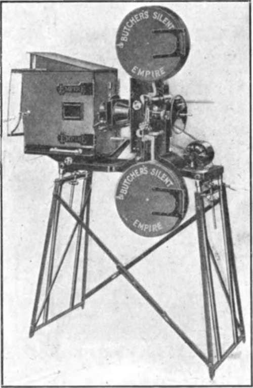
Fig. 40.
Enclosed Mechanism In Oil Bath
An accurately machined cast-iron box contains all the gearing, and forms a support to the top spool box. The gearing is totally enclosed.
The main driving gear wheel runs in an oil bath. Ball thrust washers are fitted to all the main spindles.
Masking
The picture is masked by means of a large diameter brass knob placed on the side of the mechanism. A fixed optical centre is maintained by means of a Patent whereby the beam of light from the arc, the mask and the lens are moved together in correct alignment.
Vertical Film Track
The spool boxes are placed vertically one above the other, thus forming the ideal film track. Its simplicity is its strong point; threading up is a matter of but seconds ; wear on the film is practically eliminated and, in addition, it ensures smoother and lighter running.
Further the arrangement of the gate and mask is such that the film and film loops are forward of the light trap, and well away from the heat shield.
The Film Trap
Every means has been provided to protect the film from the heat of the electric arc. The mask, being fitted behind the film, allows only one picture to be exposed at one time to the light rays. As an additional precaution a well-made metal Heat Shield with beaded edge protects the entire film track from stray light rays, and also prevents any possibility of the film touching the lamp house in the event of a breakage.
Continue to:


My Books

