


Welding Under Normal Conditions. Continued
Description
This section is from the book "Workshop Receipts For Manufacturers And Scientific Amateurs. Supplement Aluminium To Wireless", by The Chemical Publishing Co.. Also available from Amazon: Workshop Receipts For Manufacturers And Scientific Amateurs.
Welding Under Normal Conditions. Continued
23. ;The joints between the rubber or metallic tubes and the blowpipe should be carefully examined from time to time to see that they are in order, and care should be taken to see that the tubes are free and not in contact with any heated portion of the boiler under repair.
24. ;In cases where another workman is employed with a blowpipe for the purpose of heating the back of a part which is being welded, similar precautions must be taken.
25. ;All boilers should be hydraulically tested after welding, and water should not be run into the boiler until the welded part has entirely cooled down.
Note
When blowpipes are required for use in confined spaces or for working under conditions in which the heat becomes excessively hot, " P " and " R " type heads can be supplied manufactured from special heat-resisting material.
In General
26. Obtain long life and continued efficiency from your apparatus by handling it carefully ; if the nozzle end of the blowpipe is used as a lever or a hammer, leaky heads and loosened nozzles will be the result.
In the case of the blowpipe sets, proper places are made for the reception of each size head. The heads should be kept in these places and not thrown into a box loosely with other tools or heads where they are sure to get damaged.
27. No oil or grease or white or red lead should be used on the blowpipes or gas connections; oxygen under pressure in contact with oil or grease forms an explosive mixture.
Welding Cast Iron
The satisfactory welding of Cast Iron calls for more than ordinary thought and care from the operator.
An essential to success is a suitable electrode which will deposit metal having such characteristics that when the Cast Iron diffuses into the weld metal the usual excessive hardening by rapid cooling is avoided and a machinable metal is obtained.
Such an electrode is found in the Special Electrode for Cast Iron supplied by The Quasi-Arc Company. This electrode is covered by a suitable flux which cleanses and protects the Cast Iron, and also prevents the formation of a white
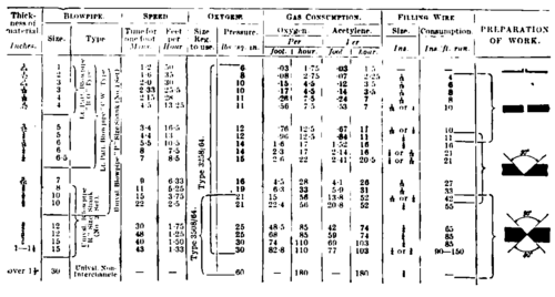
Steel Welding Table
Filling Material And Flux Table
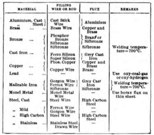
Cast Iron Welding Table

The filling material consumption in the above table is for 1/4" Ferro" Silicon or Super-Silicon rod iron junction between the added metal and the casting.
An important feature of this electrode is the softness and ductility of the metal it deposits which enables it to yield to the stresses introduced by contraction, and thus avoid fracture of the casting adjacent to the weld. Avoidance of undue heat in the weld is important to reduce contraction on cooling to a minimum, and also to minimise the loss of important constituents : this is rendered possible by the low melting temperature of the Special " Ouasi-Arc " Electrode.
Cast Iron has only one-third of the tenacity of the weld metal, and to avoid fracturing the weaker metal it is clear that the two dissimilar metals must not be directly opposed under equal conditions, otherwise " pulls " will occur. This extra strength of the weld metal may, however, be turned to account, when, it is recognised that for every square inch of fractured Cast Iron only one third of a square inch of weld metal is required to repair it.
A further point of which advantage may usefully be taken is that Cast Iron in shear has double the strength of Cast Iron in tensile. Therefore, assuming a casting of six square inches in sectional area to be fractured, if only two square inches of weld metal are applied in a manner which puts the Cast Iron in shear, cracks will be avoided and theoretically the junction would be as strong as the original casting.
It is practically impossible to prevent entirely the diffusion of carbon into the added weld metal at the junction, and it may be somewhat difficult to machine. Therefore, it is advisable to sink the welding below any face of the casting that has to be subsequently machined.
Incidentally, a great saving of time and material originally taken for chipping out and filling in a Vee will result, also a saving in the quantity of electrodes used.
By reference to the following instructions, illustrated by sketches, this method of applying " Quasi-Arc " Electrodes will be clearly understood, and (Fig. 226) shows a typical instance where this method was employed.
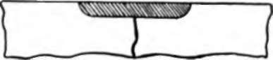
Fig. 226.
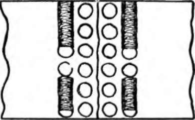
Fig. 227. The spots shown are small welds made with a No. 12 Electrode held vertically and using a current of about 75 amps., the object being to provide a distributed hold on the face of the casting in many spots and to avoid a pull on any particular place : the 75 amps., being only momentarily applied for the purpose of rapid penetration, does not unduly heat the job.
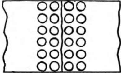
(First Stage) Fig. 227.
Note
Whether one, two or more rows of spots on each side of the fracture may be necessary will be determined by the thickness of the casting ; in many cases one or two rows may be found sufficient.
Fig. 228 shows a further stage. A series of short runs using a No. 12 Electrode with a low current (35 amps.) on the outer rows of spots of about 1/2in. in length are applied until a line of welding is completed, on each side. The additional lines of welding are made in a similar manner until the whole surface is covered but leaving the centre over the fracture unjoined.
(Second Stage)
Fig. 228.
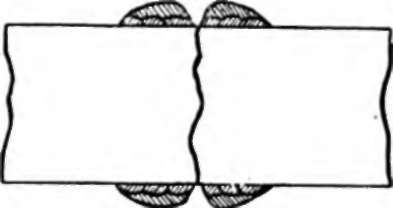
Fig. 229 shows a building up of an additional layer or layers of metal using a No. 12 Electrode with a low current (35 amps.), avoiding any junction across the fracture but forming a V as shown.
(Third Stage ) Fig. 229.
Fig. 230 shows the final stage, bridging across the V, using a No. 12 Electrode and a low current (35 amps.). For a deeper V as would be required for heavier castings, several such runs would be necessary.
It will be seen that by this method the actual pull due to cooling is on the weld metal and is distributed over the face of the casting by the spotting, thus bringing the Cast Iron partially into shear, in which direction the metal is better able to stand the light pull of the connecting bridge.

(Final Stage)
Fig. 230.
It is found necessarv at times to machine the face of a casting that has been welded. In such cases it is advisable to "sink " the face as shown in Fig. 231 and fill up the space by spotting and welding as previously described. As in some cases hardening occurs where the weld metal touches the casting, it is advisable that the faces A and B should not be touched with the electrode. The weld metal should then be hammered over to touch the Cast Iron, as shown in Fig. 231. The face will then be quite soft and machinable.
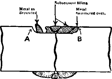
Fig. 231.
In the example illustrated in Fig. 232 the fractured gear wheel was repaired by the method shown in Fig. 231 for the space between the teeth and for the other sides, where space for reinforcement was available, the method shown in Figs. 227-231 was adopted. (The Quasi-Art Co., Ltd.)
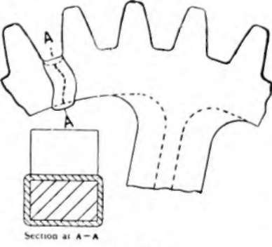
Fig. 232.
Continue to:


My Books

