Lathes With Plain Or Back Center Mandrels. Part 2
Description
This section is from the book "Turning And Mechanical Manipulation", by Charles Holtzapffel. Also available from Amazon: Turning and Mechanical Manipulation.
Lathes With Plain Or Back Center Mandrels. Part 2
The axis of the plain popit head, fig. 98, is bored out to be in precisely the same line, vertically and horizontally, with that of the mandrel; the under side of the base and the sides of the tenon, by which it takes its adjustment on the bearers being also in agreement. The holding down bolt, is permanently fixed to the tenon and has a fly nut and washer fig. 103, beneath the bearers. The hole bored through the casting in the plain popit head, is fitted with a cylindrical piece of brass, bored and tapped to receive the pointed center screw; which latter when advanced against the work, is retained in position by a binding screw above, provided with an internal brass washer to prevent injury to its threads. The pointed center screw is advanced by a loose lever, passing through a transverse hole in the head; the lever being twisted round in either direction, to advance or withdraw the screw, by the index, or the two first fingers of the right hand, straightened and placed against its shaft. A hollow center is usually left in the head of the screw, that the plain popit head may be used when turned round to stand in the reverse direction, for the support of spindles and other pointed work. A wheel or a winch handle, is often fixed upon the head of the screw, this, is more frequently done with the cylinder popit head. The lever however, as in figs. 98 and 99, is to be preferred in most cases; it is less obstructive, and with it the fingers are able to more truly appreciate the advance of the point, an advantage of some importance, especially for drilling work revolving on the mandrel, as the extent of the cutting action of the drill can then be more exactly felt and moderated.
Fig. 98.

Fig. 99.

The pedestal of the hand rest fig. 102, stands upon the surface of the bearers, to which it is fixed by a bolt, fly nut and washer, fig. 103; the head of the bolt is of dovetail section and slides freely in an undercut groove in the rest bottom. The cylindrical stem of the tee, fits into a vertical socket at the one end, and is retained fixed at the required height and angular position, by a side screw provided with an internal washer to convey the pressure. The tees for the support of the tool, sometimes called "banks," are of iron and usually vary from about two to six inches in length. The upper part slopes forward, so that the front edge stands beyond the cylindrical stem, it terminates above in a narrow horizontal surface, about a quarter of an inch wide. Two or three tees of different lengths are commonly required, and others with flat tops or of particular forms are occasionally in use.
The simple combination of parts in the hand rest, allows very considerable choice with respect to the position at which the tee may have to be fixed; and this, constantly varies with the dimensions, form and progress of the work. The holding down bolt, has the range of the length of the bearers, and of the length of the rest bottom, the latter may therefore be fixed at any place or angle upon the bearers; the tees admit of all requisite change of height and angular position, by their cylindrical stem within the socket, and the adjustments being under the control of only two screws are very readily effected.
Fig. 102.
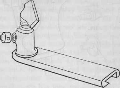
Fig. 103.

The lathe heads, may be mounted upon bearers and frames made entirely of wood. The wooden lathe bearers, although employed principally for economical reasons, also have the advantage of being easily constructed, while they are very fairly permanent; hence, they are found in very general use among the professional wood turners. They are usually formed by long parallel pieces of wood, two or three times as deep as they are wide, halved into, or attached by bolts to the wooden uprights.
The five inch center lathe, fig. 104, in which the lathe heads described, are mounted upon bearers made of hardwood, is offered as an example of a lathe fairly adapted to most plain turning; but, it must be admitted on account of the wood bearers and some other points of construction, that it is not so suitable for the more accurate works in metal, and only to a limited extent for the addition of further apparatus, such as that required for ornamental turning.
Fig. 104.

The bearers are made of two parallel bars of mahogany or other hardwood, with a parallel space between to fit the tenons of the lathe heads, the width of which is given by two rectangular pieces of boxwood, fig. 105, inlaid vertically in the uprights. The sloping ends of the bearers are received in recesses in the uprights, sloping inwards, and are attached in this species of dovetail joint by bolts, screwing into nuts inlaid in them: the construction permitting the bearers to be detached and always replaced with precision at their original distance. In replacing the bearers after the frame has been taken to pieces for packing or any other purpose; the bolts are first partially screwed up, the bearers are then driven into close contact with the boxwood blocks and the bottom of the recesses, by a few blows of a hammer, a flat piece of wood being interposed to receive the blows to avoid injury to the surfaces, after which the bolts are completely screwed up. Washers are placed under the heads of the bolts, to prevent them from penetrating the wood of the uprights. The uprights are mortised into the transverse feet, and are secured by bolts screwing into nuts inlaid in them fig. 106; the bolts also passing through one of two iron bottom bars, which assist the bearers in retaining the uprights in the perpendicular. The feet are hollowed out along their under surface, to cause the ends to rest fairly on the floor.
Continue to:
My Books

