Moulding Planes. Part 5
Description
This section is from the book "Turning And Mechanical Manipulation", by Charles Holtzapffel. Also available from Amazon: Turning and Mechanical Manipulation.
Moulding Planes. Part 5
Figs. 354.

355.

Nearly all the works in carpentry are first prepared as parallelograms of various proportions, whether they are to be subsequently used in that simple form, or to be worked with grooves, rebates, or mouldings; or to be connected by joints of various kinds. We will now follow up the formation of one flat surface, by explaining the order in which to produce the three pairs of parallel rectangular surfaces in fig. 355, namely, A a, the two faces, B b, the two sides, and C c, the two ends; and in this and every work possessing flat surfaces, it is of the utmost consequence that one face A, should be first wrought in the most careful and exact manner as above described, to serve would also agree, but B and B' would disagree; therefore the rectilinear form can only be proved to exist when A, B, and C will bear a strict comparison in each binary combination.
as the foundation or base, from which all the other measures are to be successively derived.
The works are generally sawn out a trifle above the required sizes, and the subsequent modes of proceeding, depend upon the proportions of the pieces, or whether they are thick as in carpentry, or thin as in joinery and cabinet making. In thick pieces, after the face A, has been planed quite flat, the side B is next wrought, and a short square is used to examine whether the two are exactly at right angles, for this purpose the stock of the square is rested against A, and the blade on B at various parts of the work; or indeed the square is slowly traversed to ascertain that the angle is everywhere in agreement with the square. The angle A B, is then marked with pencil lines extending on the face and side, to denote that this angle is to serve as the foundation for the subsequent measures.
Before proceeding to plane the second face a, the marking gage, fig. 842, p. 487, is adjusted until its point stands exactly as far from the head of the gage as the intended thickness of the work. The gage is then rubbed forcibly against the finished face A, so as to scratch a line on the edges of B b, indicative of the intended new surface a, and which is then worked with the same care and precaution as its companion A. After this b, is similarly worked, when the width of the faces A a, have been also scored by the marking gage applied against the true side B. En planing a and b, the square is applied from B and A respec-tively, to ensure the rectangular forms of the edges, and the gage is also used together with the square to test the parallelism of the work; and lastly, the ends C c are marked on all four sides with the square, preparatory to the use of the saw, or the formation of the tenons, mortises, or dovetails by which the parts are attached. When the works are planed with rebates, grooves, or mouldings, the squaring up of the four sides is always the preliminary step, although in some cases the principal attention is devoted to the two surfaces A B, especially when they are only required to serve for the attachment of other parts of the work.
In squaring up works cut out of thin plank, the mode is different, the pit-saw haves the board nearly parallel, and when the piece has been cut out with the hand-saw, the face A is first tried up, that is, corrected with the trying plane, the piece next gaged to thickness, either at the ends only, or on all four edges, and the second face a, is planed up. The rectangular piece is next fixed in the screw clamp of the bench, with the edge B upwards, and which is made quite straight with the trying plane in its ordinary position, and tested with the square; the two ends C c, are next marked off with the square, and planed from the corrected edge B, and lastly b is gaged and shot down to the width. By these means, should the fibres have been split, or spoiled off in shooting the ends, the removal of the edge b, as the last process would correct the evil. There are some very useful contrivances employed in planing the edges of thin works, and which will be next adverted to.
In squaring or shooting the edges of boards, the shooting board drawn in figs. 356 and 357, is very much used; it is a contrivance to enable the side A, of the work (the ends of which are shaded in each of these views), to be laid flat on a bed e, whilst the plane lies on its side, either on the bench, or upon the additional piece f; and provided the shooting board is parallel and straight, and that the sole of the plane is at right angles to its side, the rectangular forms of the edges are much more readily attained. The work is, nevertheless, examined with the square, as if the set of the iron be imperfect it will introduce a little error, and which is corrected by tapping the iron sideways, to correct its position.
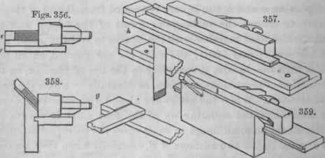
In squaring the ends C c, the transverse block g of the shooting board, is the rectangular gage, and the cross piece also partly supports the fibres from tearing away; for bevils, corresponding blocks are fitted to it as represented at h, but the mitre, or the angle of forty-five degrees there shown is the one principally required. To plain the edges, B or C, to the mitre or other angle, the respective beds upon which the work and plane are supported, are required to be to each other fan that particular angular relation, as in figs. 358 tad 359 which represent the mitre block for angles of forty-five the degrees.
These contrivances of external fences materially assist in pieces much narrower than the face of the plane, and the order in which the six faces are dressed, is very closely followed, although with different tools, in other arts, in which the works consist of like surfaces requiring a similarly strict relation to each other.
Continue to:
My Books

