On Cutting External Screws, With Screw Dies, Etc. Part 4
Description
This section is from the book "Turning And Mechanical Manipulation", by Charles Holtzapffel. Also available from Amazon: Turning and Mechanical Manipulation.
On Cutting External Screws, With Screw Dies, Etc. Part 4
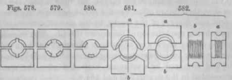
In beginning the screw, the die a, serves as a bed with guiding edges, these indent without cutting, and also agree at the first start, with the full diameter of the bolt; with the gradual reduction of the bolt, it sinks down to the bottom of a, which continually presents an angular ridge, nearly agreeing in diameter, and therefore in angle with the nascent screw. The inconveniences of the dies, fig. 581, are, that they require a large and a small master tap for the formation of every different sized pair of dies, and which latter are rather troublesome to repair. The dies also present more friction than most others, apparently from the screw becoming wedged within the angular sides of the die a.
In fig. 532, a construction advocated by Sir John Robison, the dies are first cut over a small master tap, fig. 573, the threads are then partially filed or turned out of b, to fit the blank cylinder; which therefore rests at the commencement upon blunt triangular, curved surfaces, instead of upon keen edges; and as the screw is cut up, its thread gradually descends into the portions of the thread in b, which are not obliterated. About one-third of the thread is turned out from each side of the cutting die a, leaving only two or three threads in the center, as shown in the last view; and the surface of this die is left flat, that it may be ground up afresh when blunted, and which is also done with other dies having plane surfaces.*
Mr. Peter Keir and Mr. William Jones have each proposed to assist the action of dies for large screws, by means of cutters; their plans will be sufficiently explained by the diagrams, figs. 583 and 584. Mr. Keir applied this mode to large screws of square threads for gun carriages; the dies were cut very shallow, say one-third of the full depth, and they were serrated on their inner faces to act like saws or files. The dies were used to cut up the commencement of the thread, but when it filled the shallow dies, their future office was not to cut, but only to guide the ascent and descent of the stocks, by the smooth surfaces of the dies rubbing upon the top of the square thread. The remaining portion of the screw was afterwards ploughed out by a cutter like a turning tool, the cutter being inserted in a hole in the one die, and advanced by a set screw, somewhat after the manner represented in the figures 583 and 584.*
* Select Papers of the Society of Arts for Scotland, vol. i, p. 41.
Mr. Jones employed a similar method for angular thread screws, and the cutter was placed within a small frame fixed to the one die. The screw bolt was commenced with the pair of dies which were closed by the set screw a, 583, the cutter being then out of action. When the cutter was set to work by its adjusting screw b, it was advanced a little beyond the face of the die, and not afterwards moved; but the advance of a, closed the dies upon the decreasing diameter of the screw, the cutter always continuing prominent and doing the principal share of the work.†
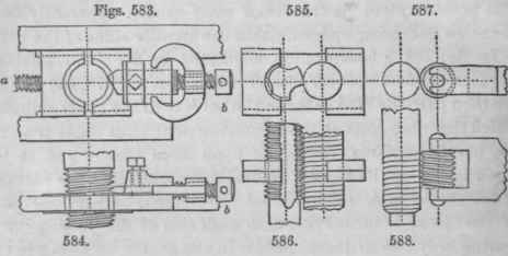
Fig. 585 is the plan, and 586 the side elevation, of an old although imperfect expedient, for producing a left-handed screw from a right-handed tap. It will be remembered the right and left hand screws only differ in the direction of the angle, the thread of the one coils to the right, of the other to the left hand; and on comparing a corresponding tap and die, the inclinations of the external curve of the one, and the internal curve of the other, necessarily differ in like manner as to direction. The mode employed therefore is to carry a right-hand tap around the screw to be cut; the temporary screw-cutter possesses the same interval or thread as before, but the cutting angles of the tap, baring the reverse direction of those of the die, the screw becomes left-handed.
* Technical Repos., vol. viii., pages 182 and 193. † Trans. Soc. of Arts, 1829, vol. xlvii., p. 135.
The one die in 5S5 and 586 is merely a blank piece of brass or iron without any grooves, the other is a brass die in which the tap is fixed; as may be expected, the thread produced is not very perfect, but in the absence of better means, this mode available as the germ for the production of a set of left-hand taps and dies. figs. 587 and 588 represent a different mode of originating a left-handed screw, proposed by Mr. Walsh; the tool is to be a small piece of a right-handed screw, which is hardened and mounted in a frame like an ordinary milling or burling tool, and intended to act by pressure alone; the diameter of the tool and cylinder should be like.*
The screw stock first patented by the Messrs. Whitworth of Manchester, is represented in fig. 589: three narrow dies were fitted in three equidistant radial grooves in the stock, the ends of the dies came in contact with an exterior ring, having on its inner edge three spiral curves, (equivalent to three inclined planes,) and on its outer surface a series of teeth into which worked a tangent screw, so that on turning the ring by the screw, the three dies were simultaneously and equally advanced towards the center.
These screw stocks were found to cut very rapidly, as every circumstance was favourable to that action. For instance, on the principle of the triangular bearing, all the three dies were constantly at work; the original tap being slightly taper, every thread in the length of the die was performing its part of the work, the same as in a taper tap every thread of which removes its shaving, or share of the material; and the dies were narrow, with radial edges, which admitted of being easily sharpened.
This diestock has been abandoned by the Messrs. Whitworth, in favour of their screw stock subsequently patented, which is represented in fig. 590. The one die embraces about one-third of the circle, the two others much less; the latter are fitted into grooves which are not radial, but lead into a point situated near the circumference of the screw-bolt; the edges of the dies are slightly hooked or ground respectively within the radius, and they are simultaneously advanced by the double wedge and nut: the dies are cut over a large original, such as fig. 576, that is, two depths larger than the screw. The large die serves to line out or commence the screw, and the two others act alternately; the one whilst the stock descends down the bolt, the other during its ascent.
Continue to:
My Books

