Sequence
Description
This section is from the book "Turning And Mechanical Manipulation", by Charles Holtzapffel. Also available from Amazon: Turning and Mechanical Manipulation.
Sequence
Plain turning of every kind requires to be followed out from the very commencement upon some plan or system, to secure the concentric truth of all the component surfaces of every individual portion of the work; a condition which also ensures the relative truth to each other of these different portions, when fitted or placed together as a whole. The precautions taken to attain these results vary in degree with the work, as that may be of an ordinary character, or requiring considerable and also permanent accuracy. They also necessarily vary in cautiousness of procedure and completeness, with the materials. For, although the same general principles guide the mode and the sequence, upon which the work may be executed in wood turning, numerous examples of both being given in following pages, whatever the system that is adopted, it requires far more exactitude and elaborate execution to arrive at equally successful results in metal.
It is necessary, first to consider the most advisable succession of steps to be adopted in the turning, and then to devise the most exact methods for the requisite successive chuckings; in which latter, lie the majority of the precautions taken for attaining final truth in the work. Unfortunately the most advisable method of chucking, cannot be invariably followed, it is therefore frequently necessary to modify the proposed method, which would otherwise be preferable, to adapt it to the means that happen to be available. The brass pulley of the mandrel of the foot lathe, fig. 113. requires exact and permanent truth, not alone for driving the mandrel, but also because its face is drilled with holes to form an accurate division plate, while various other apparatus is frequently attached to its back face, and therefore depends for its permanent accuracy of position upon the enduring truth of the pulley. The lathe pulley also affords a somewhat comprehensive example of the successive steps that may be necessary in chucking and turning in metal; the numerous processes required may therefore be consecutively and briefly referred to.
The pulley is composed of two brass castings shown in section, one the back, a hollow cone, fig. 504, formed externally in square steps, and the other, the front plate and socket or tube, fig. 505; these having been "burred" or cleansed from the sand and hammered as usual, the pulley is constructed in the following stages.
Fig. 504. Fig. 505. Fig. 506.
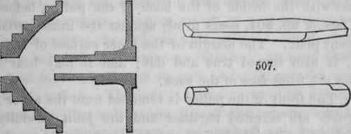
(a) The front is chucked in the universal or other chuck, held externally by the end of the socket, the left hand end in fig. 505; taking care that the plate runs true laterally. The central hole to receive the mandrel is bored, and the work being removed from the chuck, the hole is broached out to size, with the slightly taper D broach, fig. 506.
(b) A conical steel arbor, fig. 507, which may be considered for the time to represent the mandrel, is prepared, turned to size and true to its hollow centers at either end; and the socket just broached is fitted upon it; the inner side of the plate, and the exterior of the socket, are then rough turned true.
(c) The back of the pulley fig. 504, is chucked in the universal or other chuck, held externally by its smallest step, the casting being adjusted to run as true as possible, and the inside of the cone is rough turned true.
(d) The central hole at the back of the pulley, is bored out to a diameter of about one quarter of an inch less, than the external diameter of the end of the socket of the front casting; and this hole is cut with an internal screw, suitable for the reception of the socket. The work remaining in the same chucking, the narrow front surface of the shell, fig. 504, is turned true and flat, in order that it may bear fairly against the front plate when that comes against it. The chuck is removed, but the back of the pulley is left in it undisturbed, to provide for the contingency of any alteration being required, either to the face or the internal screw.
(e) The front portion of the pulley on its arbor, is again mounted between the lathe centers, placed the reverse way to fig. 505, and an external screw is cut upon the end of the socket. The length of the screw being sufficient to prevent the shoulder at the termination of the thread, coming into contact with the inside of the back of the pulley, before the front face of fig. 504, bears firmly against the inner surface of the front plate. The margin of the inner surface of the front plate, is also turned true and flat; that it may bear fairly against the front face of the back.
(f) The front of the pulley is removed from the arbor ; the two parts are screwed together and the joint carefully examined, to ascertain whether the two surfaces thoroughly fit each other around the entire external circumference of the pulley. If it be necessary, both surfaces are corrected until they do so.
(g) The two faces of the back and front of the pulley to be united, and also the external screw on the socket, but not the internal screw, are then tinned; and the two halves of the pulley are soldered to one another with soft solder, being drawn together into close contact by the screw on the socket. For this operation, the two portions of the pulley are heated on an iron plate over a fire, or preferably, because more equally, over a gas stove; the processes followed in tinning and soldering, will be found in the first volume.
(h) The arbor is replaced in the complete pulley and mounted between centers, with the face of the pulley towards the lathe head; the back surface of the pulley and the square steps, are then rough turned true. The arbor is then reversed upon its centers and the front face of the pulley rough turned; the surface of the central boss, being carefully turned true and finished.
(i) The arbor is removed from the pulley, and the mandrel for which the latter is intended is mounted between the lathe centers, and turned to the exact taper required; to precisely fit the conical hole in the pulley. The shoulder, left on the mandrel, fitting against the surface of the central boss.
(j) The pulley is replaced upon the arbor for the last time, and its angular grooves rough, turned in the square steps; a strong point tool is employed, which, after it has made some little penetration, is applied against either side of the grooves alternately.
(k) The arbor is removed, and a brass plug, about one inch in length, is turned and carefully fitted into the front end of the central conical hole in the pulley; the flat top of the plug being level with the surface of the central boss. A center mark is struck with a center punch, at any position on the line of contact of the central hole and the plug; at which center, a hole is bored about one eighth of an inch diameter, and about three quarters of an inch in depth, parallel with the axis of the pulley. The hole is therefore one half in the brass plug and the other half in the edge of the conical hole in the pulley. The plug is removed, and the half hole in the pulley is converted into a rectangular keyway, by means of a steel drift, aided when necessary by a chisel, or square files ; all burr caused by cutting the keyway being subsequently carefully removed. The key way receives the steady pin, used to prevent the pulley from moving upon the mandrel.
(L) A circular line is struck around the mandrel, about one quarter of an inch from its shoulder, and the circumference of this line is divided into two halves by the division plate, and scribed across with two short lines. The intersections are then marked with centers by the center punch, for the points of the drill and popit head; and a shallow transverse hole of about one quarter of an inch diameter, and about one eighth in depth, is bored in the mandrel to receive the steady pin.
(m) The steel steady pin, is turned to tightly fit both the depth and diameter of the hole bored in the side of the mandrel; and its projecting end is filed with two fiats on opposite sides, until it is reduced to accurately and tightly fit the square key way, previously cut in the pulley.
(n) The steady pin being inserted in its place, the pulley is again mounted upon its mandrel, and is brought up into contact with the shoulder on the latter, by the screw and nut on the mandrel behind. Being thus fixed as it will revolve when in use, the mandrel is placed between the lathe centers, with the front of the pulley to the left, or towards the lathe head. A strong point tool, firmly held in the horizontal manner, with the fingers placed as near as possible to the end of the tool, is then used to finish the grooves to size and accurately true; but, the tool is only applied to turn the right hand side of every individual groove.
(o) The position of the mandrel and pulley between the centers is reversed, that the opposite sides of the grooves, which are now to the right, may also be finished with the point tool. The opposite sides of the grooves, are thus turned alike and to the same angle, while occupying the same position with respect to the light; necessary to avoid any difference arising from optical illusion, which interferes with their being turned precisely alike, when they are not thus placed in the same direction.
(p) The mandrel is reversed, the bead or edge of the pulley, the back surface, and the shoulders of the grooves are accurately turned and finished with a flat tool; firmly held, with the fingers closely around the end of the tool to prevent vibration.
(q) The mandrel is once more and finally reversed, that the face of the pulley may be turned and finished flat with the flat tool; the edge of the central boss is finished, and the hollow at the corner turned with a round tool. This concludes the turning, leaving the lathe pulley ready for drilling the circles of holes to form the division plate, prior to engraving the figures and numbering, and the polishing.
Continue to:
My Books

