Chapter XXXII. Continuous Distillation Under Atmospheric Pressure (continued)
Description
This section is from the book "Distillation Principles And Processes", by Sydney Young. Also available from Amazon: Distillation Principles And Processes.
Chapter XXXII. Continuous Distillation Under Atmospheric Pressure (continued)
Of recent years the usual type of continuous distilling bench has been largely replaced by tubular stills or retorts. Such plants were origin-ally designed, and still find their chief application, for the working up of heavy crude oils, from which a relatively small percentage must be distilled or "topped" off in order to raise the flash-point of the residue to the point demanded for liquid fuel. Such plants are usually called "topping plants." They find a further application for the dehydrating of crude oils containing emulsions. There is no reason why such plants could not be used for the working up of crudes containing large percentages of benzines and kerosenes, and their use for such purposes is indeed being rapidly extended. Many types of such plants have been designed and are in operation, the general principle being much the same in most cases. They always operate on the continuous system, and for the space occupied and capital outlay have a large capacity.
In simple plants the crude oil to be topped or dehydrated is pumped through residue-crude heat exchangers on its way to the retorts. These latter usually consist of steel piping set in brickwork, arranged for heating by gas or liquid fuel. Evaporation largely takes place in these retorts, so that the issuing oil is more or less in the state of foam. This is led into a vessel, which may really be regarded as a vapour-liquid separator, which may or may not be externally heated by the waste gases from the furnaces. The vapours are led off from the top of this vessel and the residue from the bottom.
These plants fundamentally differ from continuous still plants, in that the complete evaporation of the necessary fractions is carried out in one operation, so that the vapours leave the residue en bloc instead of successively. As a result of this, the residue is in equilibrium with a mixed vapour which may contain light fractions, whereas the residue from a bench of continuous stills is in equilibrium with the relatively heavy vapour from the last still only. The residue from a topping plant is, therefore, likely to have a somewhat lower flash-point; or, to put it in another way, in order to get a residue of the same flash-point in both cases, a slightly higher percentage would require to be distilled off in the case of the topping plant.
Such a simple system as above described finds application specially for (a) dehydrating crude oils containing emulsion and water. The great difficulties met with in distilling such oils in ordinary stills are the risk of the contents of the still boiling over, and the slowness with which the distillation must be effected. These difficulties are eliminated in the tubular still type, as the contents of the retorts are practically boiling and frothing over all the time, (b) For topping off small quantities of distillate in order to raise the flash-point of the crude a few degrees, so that it may comply with liquid fuel specifications, (c) for the manufacture of asphalt; the advantage in this case being that the oil is exposed to the high temperatures for a few minutes only.
The advantages of the system are (a) initial low capital expenditure for a given throughput, (b) lower fuel consumption, (c) simplicity of operation.
The disadvantages are (a) the obtaining of one composite distillate, which requires further fractionation. This disadvantage has, however, been overcome to a large extent by the modification of the condensing arrangements, so as to condense the distillate in fractions, and by the introduction of redistillation plant, so incorporated with the main plant that most of the redistillation is effected by the heat of the residue. This is particularly easily effected when the percentage of distillate is small and that of the residue consequently large, (b) The necessity for closing down the whole, or at least half, of the plant in order to replace any one damaged retort tube.
This system has been developed to a large extent in America, but many such plants may now be found in operation in other parts of the world. Very full details of the operation of the topping plants in America are given in the Bulletin No. 162 of the U.S. Bureau of Mines, to which the writer is indebted for much information.
The earlier forms of plant were of very simple construction, consisting merely of: (1) A battery of retorts or stills a (Fig. 142),
(2) A separating chamber b,
(3) Condensers c, and (4) Residue-crude heat exchangers d.
One of the first plants designed to top crude oil by means other than the conventional stills, was erected in 1908 for dealing with Santa Maria oils. This process was patented by H. S. Burroughs.1 This plant consisted of a series of 12-inch pipes mounted in sets one above the other. The oil flowed through the pipes downwards, being heated by superheated steam circulating through coils placed in the 12-inch pipes. The vapours were taken off from the 12-inch pipes to condensers in the ordinary way.
A more successful type is that known as the Brown-Pickering (Fig. 143). This is composed of a rectangular still a, fitted with cross baffles, which is set in an inclined position over a furnace in which are set 3-inch pipes arranged as a coil B. The hot gases from this furnace pass under an ordinary boiler c, which is used as a preheater. The crude oil, after passing through the heat exchanger d, goes through the boiler heated by waste gases and then through the pipe retorts, eventually finding its way into the still. It follows a zigzag course through the still, determined by the baffle plates, giving of! its vapour and passing off as residue through the heat exchangers to the residue tank. The vapours, after passing through a separating chamber E (dephlegmator or fractional condenser) go on into the condenser f. Several plants of this very simple type are working satisfactorily in California.
1 Amer. Pat. 998837, July 1911.

Fig. 142. - Simple dehydrating or "topping" plant.
Several plants of the Bell design are also operating successfully in

Fig. 143. - Brown-Pickering plant.
California. These plants consist of batteries of retorts of 4-inch pipes arranged as continuous coils. The crude oil after passing first through the heat exchangers, where it is heated by residue in the usual way, flows through these retorts and thence to a separating tower, where the vapours are separated from the residue.
Each battery of retorts (Fig. 144) consists of a suitable brick setting which carries three rows, one above the other, of thirty-six 4-inch wrought-iron or steel solid drawn pipes, 20 feet long, placed at right angles to the direction of the fire gases. The pipes in each row are connected end to end by return bends so as to form a continuous coil.
The furnace is fitted with Dutch ovens so that the flames may not impinge directly on the coils. Two further sets of five rows of four 4-inch pipes, 20 feet long, similarly connected to form a continuous coil, are placed in the flues from the main furnace to act as preheaters.
The separating tower consists of a vertical cylindrical still, 6 feet in diameter, 25 feet high. The residue is drawn off through a 6-inch pipe, placed about 4 feet above the bottom. A 12-inch pipe placed about 14 inches from the top acts as vapour take-off, and a 4-inch pipe, 44 inches from the top, allows the heated frothing crude to enter. A vertical partition divides the tower into two equal compartments, from a point just above the oil inlet, to a point about 20 feet above the bottom. The condensers and heat exchangers may be of the usual type.

Fig. 144. - Bell plant.
Such a plant produces only one distillate, which naturally requires redistillation in order to separate it into marketable products.
Such a plant can handle wet oils containing as much as 20 per cent of water or more, oils which could only be handled in ordinary stills with very great trouble indeed. Such simple topping plants are designed primarily for the removal of light fractions from heavy crudes in order to raise the flash-point of the residue to liquid fuel specifications. Although they present many advantages these are set off to some extent by several drawbacks. As already mentioned, the distillate comes off en bloc as the vapours are intimately associated with the residue in the separating towers. The fractionation, therefore, is relatively poor. Residue from such a topping plant run at the same temperature as that of stills, on the same oil, flashes at about 10° F. lower temperature.
This disadvantage can, however, be largely overcome by the introduction of fractional condensation, as is applied in the modern plants working on the Trumble system. Such a system of fractional condensation has long been in use in connection with lubricating oil distillation plants, simple pipe air condensers being usually employed. A description of a modern plant working on this system is here given (Fig. 145).
The plant consists of one battery of two heaters, each containing 6 horizontal rows of 12 solid drawn 4-inch pipes, 18 feet 9 inches long, their ends being connected by steel flanged return bends, so as to make one continuous coil. These pipes are set in a brick furnace where they can be heated by the combustion of liquid fuel. The return bends outside the wall are well insulated and are, in modern plants, further enclosed in a chamber fitted with steel doors.
The outside effective heating surface of these pipe retorts is 2650 square feet. The crude oil is heated in 6 horizontal tubular heat exchangers of 556 square feet heating surface by hot condensate, and in 4 similar heat exchangers of 1600 square feet by hot residue.
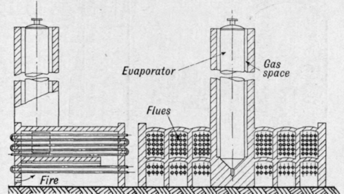
Fig. 145. - A form of Trumble plant.
The heated oil from the retorts flows to the top of a single separating tower or evaporator. In the Trumble system this evaporator is enclosed in a brickwork stack and is heated by the waste flue gases circulating in the annular space between the brickwork and the evaporator. The evaporator (Fig. 146) is a vertical cylindrical vessel, 6 feet in diameter by 25 feet high, with dished ends. At the top is a 6-inch pipe for admission of the heated crude, and at the bottom an 8-inch pipe for outgoing residue. The heating surface is 471 square feet. Inside the evaporator a central vapour-collecting 12-inch pipe supports several umbrella - shaped baffles, the object of which is to divert the flow of crude oil to the sides of the evaporator. Immediately below the umbrellas are perforations in the central 12-inch pipe to allow of the exit of the vapours which are taken off by one or more pipes to a vapour header outside the evaporator. The bottom of the evaporator is provided with a perforated steam coil, through which live steam can be blown to assist in the evaporation. An oil catcher is placed in the vapour line to return any mechanically carried spray back to the crude. The vapours, after leaving the evaporator, pass through the dephleg-mators arranged in series. Each of these (Fig. 147) is 16 x 6 feet. They are fitted internally with a number of horizontal circular baffle plates of saucer shape. Half of these are fitted closely to the inside surface of the vessel, having circular holes in their centres to permit of the passage of the vapours. The other half are placed alternately with these and are of smaller diameter without a central hole, so that the vapours pass through the annular space between the plates and the inner surface of the vessel. At the top of the dephlegmator is a water circulating coil. At the bottom of each dephlegmator is a perforated steam coil. The condensate draw-off pipe taken from the bottom of the dephlegmator is trapped by a syphon pipe, 4 or 5 feet long, to prevent the blowing out of vapours. The area of the baffle plates is 400 square feet, of the outer radiating surface of the dephlegmator 378 square feet, and of the cooling surface of the water coils 256 square feet.

Fig. 146. - Trumble evaporator.

Fig. 147. - A type of dephlegmator for Trumble plant.
In this way the crude vapours are fractionally condensed into 7 fractions, one flowing from the bottom of each dephlegmator, and one from the vapour outlet of dephlegmator 6. These condensates are dealt with according to circumstances and the nature o.f the crude. They may be led off as a ready-product, being cooled by the crude-oil condensate heat exchanger mentioned above, or they may be treated as an intermediate product and be subjected to further redistillation in the separators or in another plant. The quality of these dephlegmator condensates may be to some extent controlled and varied by the regulation of the steam and water supplied to each dephlegmator.
For example, the condensate from dephlegmator 1 may be a gas oil of high flash-point, that from 3 or 4 may be a kerosene distillate, that from 6 a benzine distillate, those from the others may require redistillation.
The separators consist of steel rectangular boxes, 18 x 6 feet x 40 inches high, with a manifold at either end connecting to a series of heating pipes which run through the box. The box is divided into six portions by longitudinal partitions about 2/3rds of the height of the box, each compartment containing six heating pipes, heating surface 3 to 4 square feet, connected to the outside manifold. The distillates to be redistilled enter at one side of the apparatus flowing through holes in the partitions at successive levels. Distillation takes place, which may be assisted by live steam, the vapours passing off by a vapour outlet from the top of the box, the residual portion (separator bottoms) flowing out at the far end of the box. Hot residue or distillate flowing through the heater pipes supplies the necessary heat.
Condensers of the usual tubular type working on the counter current principle are employed, and jacketed line coolers are used to cool the condensed distillates on their way to the tailhouse. The flow of oil through the plant is depicted on the accompanying flow sheet (Fig 148).
The crude is first pumped through three large condensers 1, 2, 3, where it is heated by vapours and hot distillates, thence through the heat exchangers 4, 5, 6, 7, 8, where it is heated by residue from the evaporator. It then enters the bench of retorts, where it passes through the pipes in an upward direction and on into the top of the evaporator column. In the evaporator the vapours are disengaged and find exit through the side vapour take-off under the umbrellas, while the residue flows out at the bottom through the residue crude heat exchangers 4, 5, 6, 7, 8. A part of the residue may be diverted through the heating tubes of several of the separators, so that its heat may be utilised for redistilling the distillates condensed in the dephlegmators. One or more of the dephlegmators may be arranged to work on the vapours from a separator. The actual arrangement of the plant and the flow of the crude, residue, and distillates depend on the nature of the crude and on the manner in which it is to be worked. A general idea only-can be here given (Fig. 149); the actual system used must be evolved on the spot. A plant such as described above would have a daily capacity of about 900 tons when distilling off 20 per cent from the crude oil.

Fig. 148. - Path of crude through Trumble plant.

Fig. 149. - Evaporator and dephlegmators of Trumble plant.
As an indication of the manner of operating the plant and of the results obtained, the following data may be given: Crude Oil distilled, sp. gr at 15° C. 0.916 (15 per cent being distilled off). Temperature of crude in evaporator 220° C. Temperature of vapours in dephlegmatorsNo. 1 . . . 185° C. No. 2 . . . 160° C. No. 3 . . . 150° C.
No. 4 . . . 120° C. No. 5 . . . 110° C. No. 6 . . . 100° C.
The condensates from these dephlegmators had the following properties :-
Condensate. | Sp. gr. | Flash point. | Percentage in Engler flask boiling up to | |||
100° C. | 150° C. | 200° C. | 250° C. | |||
D 1 | .860 | 140° F. | . . . | . . . | 9 | 40 |
D 2 | .849 | 130° F. | . . . | . . . | 15 | 65 |
D 3 | .828 | 95° F. | . . . | 7 | 47 | 92 |
D 4 | .815 | 90° F. | . . . | 14 | 80 | 98 |
D 5 | .800 | . . . | . . . | 30 | 92 | 100 |
D 6 | .787 | . . . | . . . | 45 | 96 | 100 |
D 6 issuing vapour | .750 | . . . | 29 | 90 | 100 | |
Residue | .927 | 150° F. | . . . | 1 | 11 | 15 |
The following data give some idea as to the nature of the fractionation effected by the separators: -
Fraction. | Sp. gr. | Percentage in Engler flask boiling up to | ||||||
100° C. | 125° C. | 150° C. | 175° C. | 200° C. | 225° C. | 250° C. | ||
Vapour from separator | .798 | 4 | 24 | 75 | 94 | 100 | . . . | |
Residue from separator | .835 | ... | ... | ... | 1.5 | 44 | 82 | 96 |
One of the great advantages of a modern Trumble plant is the low working loss. This is a result of the compactness and continuity of operation of the plant.
Products requiring redistillation are not stored, allowed to cool and again reheated, but are redistilled as they are made, so that the system embodies the functions of a continuous bench and redistillation stills all in one. In the working up of a crude yielding 2 1/2 per cent of benzine, and 16 per cent of other distillates, a working loss of only 0.8 per cent of the crude oil was obtained.
A further advantage is the relatively low fuel consumption consequent on the efficient manner in which all possible heat content of vapours and residue is utilised, e.g. in working up a crude which yields 20 per cent of distillates only 1.1 per cent of oil fuel was used directly in the plant. This represents an over-all efficiency for the plant of 57 per cent, a figure which exceeds that of a plant of conventional stills, though with similar arrangements for fully utilising the waste heat of the flue gases, residues, and distillates there is no reason why the thermal efficiency of a bench of stills should not be as high.
Topping or distilling plants of this type are decidedly cheaper as regards both capital outlay and operating costs than stills of the conventional type. Under the present unsettled conditions, however, with constantly varying costs of fuel, material, and labour, it is impossible to give any figures of value as to the operating charges of any plant.
References
J. M. Wadsworth: "Removal of the Lighter Hydrocarbons from Petroleum by Continuous Distillation." U.S. Bureau of Mines. Bulletin No. 162, 1919.
A. F. L. Bell: "Important Topping Plants of California." Transactions Amer. Institute of Mining Engineers, Sept. 1915.
J. M. Wadsworth : " Construction and Operation of Toppers of Bell Design." Nat. Pet. News, Feb. 4, 1920, p. 33.
Continue to:
My Books

