Stills And Distillation In Practice. Part 4
Description
This section is from the book "Distillation Principles And Processes", by Sydney Young. Also available from Amazon: Distillation Principles And Processes.
Stills And Distillation In Practice. Part 4
Rectifying Columns
The various methods adopted, though they differ greatly in details, all make use of one or more fractionating columns, from which the fractions to be collected are drawn off simultaneously. The columns used may be classified, as in the case of the wash columns, under the following types:
1. Plate Columns.
2. Sloping Columns.
3. Film Columns.
4. Spraying Columns.
1. Plate Columns. - The two types already described under wash columns are frequently employed for rectifying columns.
Both types give good results, but the plates with perforations (Fig. 106) have the disadvantage that the vapour rising through the perforations tends to carry small drops of liquid with it on to the plate above. This objection is overcome by the construction shown in
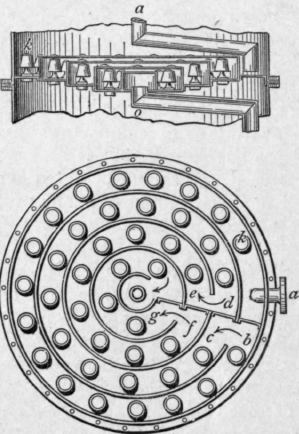
Fig. 112.
Fig. 107. In this case the vapour passes horizontally into the liquid on the plate, and splashing up of liquid on to the plate above is reduced.
In some cases the flow of liquid on the plate is directed by baffles so as to ensure an even distribution and mixture with the rising vapour. To this class of plate belong those designed by Egrot, Fig. 112. Tables 106 and 107 show the number of plates required under various working conditions.
2. Sloping Column. - The sloping column already described may also be used for rectifying purposes.
3. Film Columns. - Ilges has made use of towers packed with glass balls as rectifying columns. As pointed out by Tungay,1 the nature and arrangement of materials used for packing such towers is of importance. The packing should be composed of units of regular form. There should be a large free space compared with the total volume of the column filled. The packing should not be acted on by the vapours in contact with it and should not be brittle. Direct free passage of the vapour should be avoided. Continual change of velocity of the vapours should be produced so as to effect thorough mixing.
These objects are well attained by Raschig rings (see Fig. 113). These consist of thin sheet-iron rings, 1 inch in diameter and 1 inch long. They are arranged promiscuously, and give a scrubbing surface of 200 square metres per cubic metre of space filled. The free space is also large, amounting to about 90 per cent of the total space filled. Lessing's rings (Fig. 113a) give an even larger scrubbing surface.

Fig. 113.

Fig. 113a.
4. Spraying Columns. - A form of spraying column has been designed by Egrot, E.P. 3561, 1903, and is shown in Fig. 114.
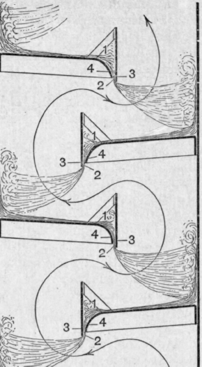
Another type of spraying column has been invented by Dr. K. Kubierschky, E.P. 15300 ; 1913. Shown in Fig. 115.
The column is divided into separate chambers by strainers 30, 31, which allow the trickling liquid to pass down, but do not allow the gases to rise. The sieves 30, 31 are arranged alternately. The sieves 30 carry axially disposed tubes 32, which lead from the lower strainer 31, namely the base of the lower compartment, to the top of the compartment above, that is to say, to the next sieve 31 above.
The sieves 30 are arranged in annular sleeves 33, which allow an annular channel 36 to be mounted between themselves and the casing of the column apparatus, so that said annular channel leads from one sieve 30, that is, from the base of one compartment, to the next sieve, and consequently to the top of the next compartment. Steam and vapours entering the lowest tube 32 pass, owing to the arrangement of the central tube 32 and the sleeves 33, in the direction indicated by the arrows. It will be obvious that in the several compartments the vapours will descend with the downward trickling liquid and will be forced on the bottom of each compartment towards the column casing by vapours following. The vapours then ascend through the annular channel to the top of the next compartment, to then again pass down in the same direction as the trickling liquid to the base of the compartment and thence through the centrally arranged pipe 32 to the top of the next compartment.
1 Chemical Age, 21.6.19, p. 11.
FlG. 114.

Fig. 115.
It is stated by S. J. Tungay,1 that this type of still was used by Messrs. E. Merck of Darmstadt for the distillation of alcohol, and that good results were obtained.
The vapour is compelled to pass from a point low down in each chamber to the chamber above. Vapour rich in alcohol and having a higher density than the steam is supposed to collect in the lower part of each chamber. By drawing the vapour
1 Chemical Age, 21.6.19, p. 11. from the lowest possible point, a more rapid concentration of the alcoholic vapours in the column is said to be effected. But with the turbulent motion in each section, differences of density would probably have very little influence.
Dephlegmation or Partial Condensation of the Vapour The fractionating columns used for the purification of alcohol on the manufacturing scale are so large that they cannot depend, as many laboratory columns do, on the cooling effect of the surrounding air to provide the necessary condensed liquid on the plates. The necessary condensation is generally provided either, as in Coffey's still, by causing the cold fermented wash to flow in a pipe running in a zigzag course over every plate of the rectifying column, or, as in most of the French and German stills, by means of a de-phlegmator placed so that the liquid condensed flows back to the top of the rectifying column. Theoretically the latter arrangement, from the point of view of fractionation, is the most efficient and economical (see p. 273).
The construction of and effect produced by the dephlegmator have already been considered (see p. 272).
If the fractionating column is efficient, the form most frequently employed consists of a simple multitubular condenser. The cooling liquid passes through the tubes and the vapour between them. The condensate is returned to the top plate of the column and the uncondensed vapour passes to the cooler.
If it be desired to reduce the height of the column, some form of dephlegmator is employed which exercises a certain rectifying action on the vapour entering it from the column. Fig. 116 represents Verchow's dephlegmator. The wash to be distilled enters at a and follows a spiral course down the annular space h. It flows away by B to the wash column.
The vapour from the column enters at c and passes up the annular space g, where it is partially condensed owing to the presence of the cold wash on the other side of the plate k.
The uncondensed vapour passes into the vessel m, which is entirely surrounded by water, which also completely fills the space s, s, s. Part of the vapour entering m is condensed and returns to G by the pipe c'; the uncondensed vapour passes out of the dephlegmator by d and is conveyed by means of a pipe to a condenser.
Continue to:
My Books

