Brick. Part 4
Description
This section is from the book "The Engineer's And Mechanic's Encyclopaedia", by Luke Hebert. Also available from Amazon: Engineer's And Mechanic's Encyclopaedia.
Brick. Part 4
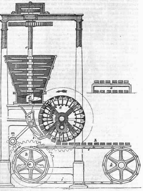
The moulding boxes, immediately they are thus filled, are subjected alternately to the action of a steel scraper, which levels and smooths their surface, and is made to operate by the pressure of springs. The bricks, now completely formed and fast in their moulds, pass downwards in their revolution, which brings the ends of the rods under the operation of a cylindrical roller, with grooves made round it at equal distances; into these grooves the ends of the rods successively pass, which in their revolution force out the rods, and thereby push out the bricks from the moulds on to boards placed underneath to receive them. The bricks thus made are carried forward to the hacks or drying house, upon an endless web or chain i i, to which a continued motion is communicated by the revolution of the two polygonal drums or wheels k k placed at the requisite distance asunder. The upper part of the engraving shows a side elevation of the machine, and the lower part a section of it; and although these views serve to give a general idea of the construction of the apparatus, it has been impracticable to show the gearing by which the several motions are produced; we will therefore attempt to describe it as follows: Upon the horizontal shaft a (which makes 2 1/2 revolutions per minute,) is fixed a toothed, bevelled wheel, which drives a bevelled pinion or. an upright shaft (not shown); nearly at the top of this a spur wheel is fixed which works into a pinion fixed upon the upper end of the hollow shaft c, which carries the knives or blades in the pug mill.
Upon the upper end of this upright shaft is also fixed a pinion, which works into an intermediate pinion turning upon an axis. This intermediate pinion acts upon another pinion affixed to the internal shaft, communicating a slow and reversed motion to it, and also the circular inclined plane affixed to it; at the lower end, on the main horizontal shaft, is fixed a spur wheel m, which gives motion to the crank and to the flap forcer connected to it. o, in the separate figure, gives the form of the shelves comprising the drying apparatus, - Mr. Leahy proposing to dry bricks either by flues or by steam, instead of ranging them in hacks exposed to the variations and inclemences of the weather, - by which means it is presumed that the bricks will be rendered dry enough for burning, either in kilns or clamps, in a much shorter time than in the common method, and the process may be carried on in winter as well as in summer. If drying by flues be resorted to, a drying house must be furnished with proper stages, and shelves must be provided. Around and across the lower part of these, flues framed either of bricks or cast iron are to be placed, through which flame or heated air is to be conveyed.
In drying by steam, the vapour is conveyed from the boiler through cast iron pipes throughout the drying house, and boards are arranged upon stages (similar to those in the separate figure), so as to leave intervals between the rows of bricks, and to prevent their touching one another.
Nash's Patent Brick-making Machinery. This invention, which we have now to describe, is the only one we believe that has yet been brought into successful operation; - owing probably to the circumstance of the patentee (who is a large tile and brick manufacturer at Market Rasen, in Lincolnshire,) having perseveringly applied that intimate knowledge of his art which can only be acquired by long practical experience. The leading features of Mr. Nash's mechanism consist in the application of separate or detached moulds of a particular construction to a series of mould boxes, which are consecutively brought into action, in the employment of heaters, placed in contact with, or contiguous to, the fresh bricks, during the process of their being moulded; and in lieu of sand, which is generally used to prevent the adhesion of the bricks to the moulds, employing elastic absorbent substances, such as cloth saturated with water. In the subjoined engravings, Fig. 1 represents a front elevation, and Fig. 2 an end elevation of the principal parts of the machine.
A vertical shaft a is made to revolve in the cylinder or pug mill b by any adequate force acting upon the bevelled wheel c.
A number of broad steel or iron blades d d d are attached to the shaft a, their surfaces being set at such an angle as will cause them during their revolution to pass nearly in contact with the edges of two other sets of knives e e e fixed on opposite sides of the cylinder, by which means the clay and other materials with which the mill is charged are tempered and amalgamated, and then forced into the hopper f, fixed to the lower extremity of the pug mill. This hopper is divided into two equal chambers by a vertical blade or knife, which separates the materials into equal portions, which are supplied to the moulds in a compact state. The moulds are lodged in rectangular cavities at equal distances in the periphery of two polygonal drums g h; these cavities are marked 1 to 12. To one face or side of the drums are attached two toothed wheels, gearing into each other so as to revolve in opposite directions when motion is communicated to one of them. These wheels lying at the back of Fig. 1 cannot be seen, but one of them is shewn at i in Fig. 2. The moulds, after being filled with the plastic material, are pushed out from their recesses by means of pistons at m m, easily fitting the recesses, and sliding upon parallel rods fixed to the rims of each drum.
To each piston is attached, by a short rod, a cross head, sliding upon the parallel rods, and having at each end small anti-friction wheels p p, which, by the motion given to the machinery, come in contact with a larger wheel q placed eccentrically, which thus raises the pistons, and the moulds which lie upon them are then removed by hand and emptied. During this latter process the emptied mould receiver will have passed over the centre of the eccentric wheel q, and the piston will be descending when the attendant places the emptied mould in its former situation, to be filled again from the hopper as it passes under it Between each of the rectangular mould boxes are formed a series of wedge-shaped boxes, termed by the patentees "hollow sectors," into each of which is placed a red-hot iron, the object of which is to expel the superfluous moisture from the newly-formed brick, etc. in order that the manufacture may be conducted in the winter as well as the summer. These irons are heated in the kiln fires.
Continue to:
My Books

