Miscellaneous Movements. Part 2
Description
This section is from the book "Scientific American Reference Book. A Manual for the Office, Household and Shop", by Albert A. Hopkins, A. Russell Bond. Also available from Amazon: Scientific American Reference Book.
Miscellaneous Movements. Part 2
181. Another device for producing rectilinear movement of a pump rod. The rod, instead of being directly connected to the working beam of an engine, is connected thereto by cross links. This motion, however, is not a true "parallel motion," but the rod is strained by cross connection.
182 to 184. Devices for overcoming "dead" centers of cranks. In Figure 182 the pitman is connected to one end of a leaf spring, whose other end is connected to the crank disk. The
Copyright. 1904, by Munn & Co.
pitman is thus permitted to play between two socket lugs projecting from the face of the disk. Just before the back center is reached, the pitman slips out of engagement with the lower socket, by reason of the tensile strain on the spring, then on the return stroke, the connection of the spring being above the line of centers, the spring yields and throws the pitman back into the lower socket, and acts upon it to rotate the disk, until the forward center is reached, when the action will be the reverse of that just described. In 183 the pitman is attached to a plate secured to the flywheel at two points by screws passing through slots cut diagonally in the plate. In starting the wheel from either of its dead centers, the pitman will cause the plate to slide on its diagonal slots and the pitman will thus carry itself out of the dead center. The plate will then be returned to normal position by a spring. The device shown in 184 is specially applicable to machines operated by treadles. Attached to the pitman is a piston acting in a cylinder pivoted to the rod on which the treadle is hinged. Within the cylinder are two coil springs which alternately act on the piston to carry the crank over the two dead centers.
185. A device for transmitting motion from one shaft to another lying at right angles thereto. The driving shaft is formed with a spiral ribbon which acts between rollers radially mounted on a wheel, carried by the driven shaft. The wheel is formed with a double series of rollers, one on each side of the spiral shaft, but the forward series has been cut away in the illustration to show detail. The action is similar to that of a worm and worm wheel, but friction is reduced by the use of the rollers.
186. An internal worm gear is here shown which offers the same advantages as the internal spur gear, namely, that of greater strength due to the fact that the area of contact between the worm and the worm wheel is increased. The worm wheel is made up of two hollow sections, clamped together, but so spaced as to form a slot in the rim through which the worm shaft passes.
187. Means for converting rotary motion into rocking motion. The power shaft carries two cams formed with corrugated peripheries. On opposite sides of the rock shaft are two rollers, one for each cam. The cams are so spaced that when one roller is being lifted, the other will fall. Thus, a rocking motion is imparted to the rock shaft. The same effect may be produced by using a single broad cam for the two rollers, but spacing one roller a little in advance of the other on the rock shaft.
188. Another form of internal worm gear. A worm wheel is mounted on a stationary bracket and engages the spiral thread formed in a ring. As the ring revolves about the gear, the latter is caused to slowly rotate. As in Figure 186, a very strong construction and powerful transmission is afforded by this arrangement
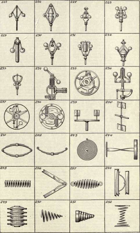
189. A sliding toggle movement is here shown for producing great pressure in a direction at right angles to that of the impelling force. The toggle members are so mounted and are of such shape that they combine the action of the inclined plane with the ordinary toggle action.
190. Means for giving parallel movement to the paddles of steamboats, etc. The power shaft carries a disk which is connected by a series of hinged links with a ring held eccentrically to the shaft, between pairs of rollers. The paddles are attached to the links and are thereby kept parallel, while the disk and ring rotate. This same arrangement can be used to communicate motion to shafts lying out of alignment with each other, one of the shafts being attached to the ring.
191. Device for transmitting motion from one shaft to another at decreased velocity. The device is here shown diagrammatically. The driving shaft carries an eccentric A, upon which spur gears B and C are fitted to turn freely. The latter are permanently secured together. Wheel B meshes with internal gear D, on the driven shaft, and wheel C meshes with the stationary internal gear E. In operation the eccentric carries gear C about gear E, thereby causing it to rotate on its own center. The gear B will be revolved by the eccentric in one direction and be rotated in the opposite direction by the gear C to which it is attached, thus causing the gear D to move at a reduced speed,
192 to 196. Ball-bearing Devices. - In 192 is shown a ball-bearing knuckle joint consisting of a flanged socket member having sockets for the reception of steel friction balls, and a second member formed with flanges which bear against the friction balls. When the device is in operation, the balls will roll back and forth in their sockets at each rotation of the knuckle joint. In 193 a common form of ball-bearing is shown. The balls are held in stationary cups and bear against cones on the rotating shaft. 194 shows an end-thrust ball bearing of common form. 195 shows a ball-bearing wheel or caster. The balls are arranged to travel over an endless path, being guided from the forward end of the wheel bearing, through a passageway in the body of the caster, to the rear of the wheel bearing surface. 196 shows the same principle applied to a worm and worm wheel. The thread of the worm does not engage the teeth of the worm wheel, but communicates motion thereto through a series of balls. The latter, when they reach the end of the worm thread, are guided back through a passageway in the worm body to the beginning of the thread.
Continue to:
My Books

