Miscellaneous Movements
Description
This section is from the book "Scientific American Reference Book. A Manual for the Office, Household and Shop", by Albert A. Hopkins, A. Russell Bond. Also available from Amazon: Scientific American Reference Book.
Miscellaneous Movements
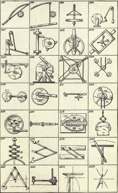
169. Device for transmitting reciprocating motion from one pair of rods to another pair lying at right angles thereto. The rods are all connected by links so that when two opposed rods are moved inward or toward each
Copyright, 1904, by Munn & Co.
other, the other two rods will be moved outward, and vice versa. Also if two adjacent rods be moved the one outward, and the other inward, the opposite rods will be moved one outward and the other inward respectively.
170. Means for converting rotary into reciprocating motion. A bent shaft carries at its outer end an arm which is loosely mounted thereon. The lower end of this arm engages a slot in a bar which is mounted to slide in suitable guides. As the bent shaft rotates, the arm which is prevented from rotating with the shaft is given a rocking movement in the direction of its axis, and thus imparts a reciprocating movement to the bar.
171. Movement used on hand stamps. The plate which carries the type normally lies face upward against an ink pad, and is formed with a flange at each end in which cam slots are cut. The type plate is pivoted in a yoke piece to which the handle is secured, the pivot pins passing through slots in the uprights of the frame. When the handle is depressed, the type plate is carried downward and at the same time rotated by engagement with two pins which operate in the cam slots so that the type will face downward when brought into contact with the paper. The parts are returned to normal position by a spring on release of the handle.
172. A peculiar device for alternately rocking a pair of levers by means of a reciprocating rod. The rod carries a bell crank lever, A. This lever is normally held in the position illustrated by two pins against which it is pressed by the spring-pressed rod. Two bell crank levers, B and C, connected by a bar, are hinged adjacent to the rod. With the parts in the position illustrated, when the rod is drawn forward, one arm of the bell crank, A, will engage a pin at the end of lever, B, and will be thereby turned until it engages a stop piece, D, on the rod, after which it will operate to swing bell crank, B, on its axis. Owing to the connection between the levers B and C, the latter will also be swung but in the opposite direction. On return of the rod the bell crank lever, A, is brought to normal position by the two position pins, and when next the rod is drawn forward, the other arm of lever A will engage a pin on lever C, returning both levers B and C to their original positions.
173. Mechanism for transmitting rotary motion at increased speed from one shaft to another in alignment therewith. The lower or driving shaft carries a crown wheel at its upper end which is engaged by a second crown wheel having universal joint connection with a stationary central post. The latter is supported from the frame by cross arms, which are adapted to engage slots cut in the second crown wheel, and thus prevent the wheel from rotating. The upwardly projecting frame of the second crown wheel is connected to a wheel on the upper shaft, but eccentric thereto, by means of a ball-and-socket joint. The driven crown wheel is thus tilted so as to engage the teeth of the driving wheel. As the latter rotates the driven wheel is given a rocking or wobbling movement, which rotates the upper shaft. A slight movement of the lower shaft thus produces a complete rotation of the upper shaft.
174. A device for converting reciprocating into rotary motion and vice versa. Two intermeshing gear wheels are provided with spring pawls oppositely disposed on the gears, and adapted alternately to snap into engagement with a lug on a reciprocating rod and thereby impart rotary motion to the gears.
175. A device for spacing apart a number of bars. The bars are arranged to slide with a certain amount of friction between guide pieces. Normally they are crowded together in a group by a pair of coil springs. A pair of rotating spur wheels whose teeth engage the pointed ends of the bars are mounted on either side to slide vertically in suitable guide-ways. The vertical movement of the gears carries the bars downward against the springs and the slow rotary movement of the gears successively releases the bars at regular intervals. The bars remain where released, being held by frictional engagement with the guide pieces.
176. An early form of flexible shaft coupling. One of the shafts is pointed and fits into a socket in the other shaft. Each shaft carries a collar and these are connected by a flat spiral spring.
177. Centrifugal hammer. Two hammers are hinged on a rapidly revolving disk. As the disk revolves, these hammers are alternately swung by the added force of gravity and of centrifugal action, on to the anvil. A very powerful stroke is thus given.
178. A device for communicating reciprocating motion of an engine to a rotating crank in such manner that the crank will have a greater throw than the stroke of the engine crosshead. The connecting rod acts on the crank shaft through a "lazy tongs" which multiplies the stroke and affords a better leverage upon the same.
179. A device for producing two rotations of the crank shaft of an engine at each complete (forward and return) stroke of the cross-head. The crosshead of the engine is connected by a rod to a pair of connected levers, one of which is pivoted on a fixed pin and the other to the working beam. Owing to the toggle action of the levers the working beam will rise and fall twice while the crosshead moves to its outer position and returns.
180. A device for converting rocking movement into rectilinear reciprocating movement, usually called "parallel" motion. Two links pivoted on the fixed pin A connect at their outer ends with two links pivoted on a rod at D. The latter links are also connected to a pair of links pivoted to a rock arm C. The distance between A and B, the fixed pivot of the rock arm, is equal to the distance between B and C. Owing to the fact that the double link-quadrangle swings on two pivots, it will be lengthened when swung out of the vertical position, thus giving a rectilinear motion to the rod D. This movement is called "Peaucellier's" parallel motion. It is used to give rectilinear movement to a pump rod or to the piston rod of an engine.
Continue to:
My Books

