Direct Supply
Description
This section is from the book "A Working Manual Of American Plumbing Practice", by William Beall Gray, Charles B. Ball. Also available from Amazon: Plumbing.
Direct Supply
The salient features of the supply system for city pressure, not already mentioned, are; separate shut-off cocks for the supplies of each fixture; separate lines to each isolated fixture or to each group of fixtures; 3/4-inch supply to all sinks, trays, and baths; 1/2-inch supply to water-closet tanks; and 1/2 or 3/8-inch branches for lavatories; no traps in supply lines; return circulation from lavatory hot supply so that hot water can be drawn instantly at the lavatory faucet; storage cylinder for hot water amply large to furnish a hot bath without robbing the hot service for other purposes; faucet on sediment pipe, so that water can be drawn at that point when desired; and proper stove connection. All shut-offs in direct-pressure work, except where located 'immediately at the fixture, should be stop and waste, with the waste on the house or fixture side.
On single runs of lead pipe, make all bends on the same size of pipe, of the same radius. Make no bend on any size pipe, except tubing, of less than 3-inch radius to the center of the pipe. Give J and 3/4-inch pipe bends 3-inch radius; and 7/8 and 1-inch pipe bends, 4-inch radius. Where two pipes of different size run together and bend in opposite directions, give the bend of the smallest pipe the radius prescribed for the bend in the larger one, if practicable.

Fig. 73. Method of Laying Out Con-centric Bends in Parallel Pipes..
Table III Data Relating To Offsets In Iron Pipe Work
Bend | Equal to | Multiply by |
1/6 .............. | .. 60° ............ | 1.15 |
1/8 ................ | .. 45 ° ............ | 1.414 |
1/12............ | .. 30 ° ............ | 2.00 |
1/16............ | .. 22 1/2° ............ | 2.61 |
1/32............. | ll 1/4° ............ | 5.12 |
1//64 ................ | .. 5 5/8°............ | 10.22 |
Where more than one pipe bend in the same direction, make the bends of the pipes form arcs of concentric circles as shown in Figs. 73 and 74. To set off the offsets in Fig. 74, draw line A, at the end of the first bends; and with the proper radii, describe the arcs that outline them. Set off one-eighth of the circumference of the circle corresponding to the larger arc, and draw line C, cutting the center of the circle. Then produce dotted line D, and set off a square the diagonal of which will give the straight pieces of the offset desired; and produce E parallel to C- Next describe the arcs outlining the second bends, finding the center on E from radius equal to the corresponding radius at A, which will be the intersection for E and B. This brings the offset parts the same distance apart as the runs are. To accomplish this result with iron pipe, the centers of 45-degree fittings would have to be placed at the intersections of tangents of the arcs extended, thus throwing the fittings in a line deviating 22 1/2 degrees from one perpendicular to the run. This plan is the strictly correct way for iron pipe, as well as lead pipe work; but on account of the

Fig. 74. Method of Laying Out Offset in Parallel Pipes to Preserve Equal
Distance between Them difficulty of laying out the work, it is more usual to line up offset fittings perpendicular to the runs, and let the offset pieces fall, as they will, nearer to each other, center to center, than are the lines of the runs.
Offset pieces from center to center of fittings exceed in length the distance offset in the ratio indicated by the constants given in Table III. To find the length of an offset piece, center to center of fittings, simply multiply the distance the line is to be offset, by the constant given for the particular fittings to be used.
Water Supply to Fixtures. In a small installation, the running of a separate supply to each fixture is desirable. There is, however, a limit to the number of fixtures and isolated location of them, beyond which the furnishing of separate supplies to each faucet is folly, as in addition to the confusion of pipes, and the expense, it leaves more material open to possible failure, and does not reduce the chances of lack of service in porportion. The sole object of separate supplies (and of cocks, too) is to avoid losing the service of other fixtures during times when one of them, or its supply or waste, must be repaired.
In a residence job, two main supplies to each bathroom, with separate stops for each fixture, are sufficient; and a return circulating pipe from the lavatory will serve every purpose, as the water is kept hot in the main line to the bath branches.
The pump and kitchen-sink work of a country job of this type is shown in Fig. 75. The pump air-chamber discharge leads up to and over tank. An opening near the pump provides for elevating water by other means if desired. The pump faucet is piped up and over so as to discharge into sink. The tell-tale pipe from tank leads down behind sink-back and out through a nozzle, as shown. The sink supplies are fitted with stop-cocks. The pressure being light, there are no air-chambers to the sink faucets. The supply to pump is from a large cistern.
Fig. 76 shows the supplies of the same job, on the kitchen ceiling. The system provides positive circulation to keep hot water near the bathroom fixtures. The hot supply is on the left side for each fixture.. There is only one pipe crossed, and it does not interfere with draining the job. There are no traps in the supplies, nor drain cocks, to be forgotten. There is a relief line from the reservoir to the tank, so that it is not possible to close every means of escape for vapor or steam from the reservoir. The hot supply and cold service are both open to the air at the tank.

Fig. 75. Pump and Kitchen-Sink of a Country Installation..
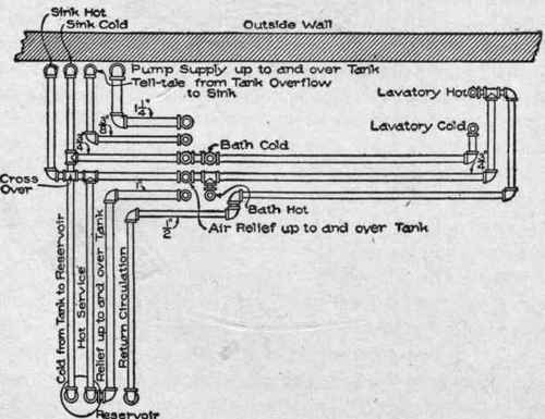
Fig. 76. Plan Showing Layout, on Kitchen Ceiling.of Supply Pipes in Installation.
Continue to:
My Books

