


Observations On The Construction Of Bridges. Continued
Description
This section is from the book "Elementary Principles Carpentry", by Thomas Tredgold. Also available from Amazon: Elementary Principles Of Carpentry.
Observations On The Construction Of Bridges. Continued
347. Fig. 7, Plate XLVII., shows a method similar to that adopted for the timber arches of a bridge of 49 feet span over the Thames near Kingston, erected in 1570. Combinations of this kind naturally lead to the continued curved rib, which possesses advantages not to be found in a series of beams merely abutting end to end; for when the rib is built of short lengths, with the joints crossed, and the several thicknesses firmly bolted together, it becomes nearly as strong as a solid beam. If the straining force be applied at D
Fig. 7.
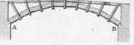
Fig. 8
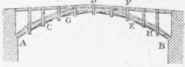
Fig. 9.

Fig. 10

Fig. 11

Fig. 12.


(Figs. 8 and 9, Plate XLVII.), it must be sufficient to fracture the rib at C, D and E; therefore, when the strength of the rib is capable of resisting the strains at C, D and E, and the curve is a proper curve of equilibrium to the constant loal, this combination is both secure and simple. Its strength to resist a moving load would be much increased by the addition of braces between the upright timbers which connect the roadway to the arch. The use of curved ribs of this kind was known at a very early period, and the system has been further improved by bending the pieces that form the ribs. Bridges of considerable span have been constructed on the principle shown by Fig. 9, as that of Wiebeking's, over the Regnitz, near Bamberg, shown by Plate XL., which was 208 feet between the piers.
348. When the span is considerable, owing to the tendency of a curved rib, in the case of a central or a moving load, to yield at D, C and E (Fig. 8), the strength must be increased by adding to the depth of the rib, which may be accomplished in the manner shown by Fig. 10. The upper and lower members of the rib are connected by radial pieces, and the intermediate space filled in with diagonal braces. In such a case the two curved beams must be continuous and put together so as to resist either extension or compression. With this form no thrust is sustained by the upper rib at the abutments, nor by the under rib at the crown. An advantageous mode of constructing the ribs is with thin lamina, as originally suggested by M. de-Saint-Phar, and used in roofing by Emy (see Art. 242, Sect. IV.).
In cases where it is difficult to form abutments of sufficient strength to enable the tie to be omitted, and it is desirable to keep the headway under the bridge as high as possible, the arched rib may be placed above the roadway, as shown by Fig. 11, Plate XLVII.
Several wooden bridges in America have been constructed with arched ribs, and of late years the timber arch has been ranch used to strengthen the lattice and frame bridges of that country.
When the width of the bridge is considerable, a rib may be placed in the middle, so as to divide the roadway into two parts, one being used for the up and the other for the down traffic. The whole may be roofed, or the ribs merely covered, as shown at a da' a" (Fig. 11, Plate XLVII.).
349. Again, starting from the principle of the straight beam (Art. 346) we arrive at the system of open framework, with horizontal top and bottom strings, as adopted in America. In this form the material to resist compression and extension is placed at the greatest distance from the neutral axis, and consequently the greatest strength is obtained with the least quantity of timber. But as two longitudinal beams merely placed at a certain distance apart, would not act together as a single beam, it is necessary to connect them, as shown by Fig. 12, Plate XLVII.
Each pier has to support a portion of the load on the bridge. This load acts in a vertical direction, and causes a corresponding reaction of equal amount in the girders of the bridge itself, which modern writers on the theory of bridge construction have called the "shearing force," as it tends to cause a separation or shearing of the girder throughout its whole depth at the points of support where it is greatest.
In a solid beam the consideration of the shearing force is usually neglected, owing to the quantity of material near the points of support being more than sufficient in proportion to that in other parts which have to resist cross-breaking or bending; but when that material is reduced, as in the open beam, the case is altered, and the effect of the shearing force becomes important. In several of the earlier American lattice bridges, failure resulted from neglecting to provide for it. Obviously the amount of the shearing force at the points of support is equal to the weight supported by each, that is to say, in a beam uniformly loaded it would be equal to one-half of the gross load, and it decreases gradually towards the centre, where it vanishes.
When the load is applied at the centre, the shearing force is also equal to one-half of the gross load, but is constant at every point.
If the load is applied at any other point than the middle, the shearing forces on either side are equal to the pressures on the points of support, and are also constant.
The force we have described being vertical will increase on being transmitted through the inclined beams or braces a, a, Fig. 12, which compose the intermediate parts of an open beam, in the proportion of the length of the inclined brace to the vertical height above its base.
The equal horizontal strains of compression and extension in the open beam are concentrated in the top and bottom strings; they are greatest at the middle of the length when the load is on the middle or uniformly distributed over the length. In other cases the greatest horizontal strain is near the centre of gravity of the load (see Fig. 54, Art. 189).
350. When the opening or distance between the points of support does not exceed 20 feet, a bridge may be constructed by simply laying balks of timber across it of about 12 inches square, trussed with iron rods as shown by Fig. 84, Art. 264. The number of these balks in the width of the bridge will depend on the load to be supported; their scantling may be calculated by the rules given in Art. 264. The strength may be increased by trussing the railing on each side of the roadway. For spanning wide openings, other methods are to be preferred.
351. Where the width of the opening does not exceed 50 feet, curved ribs composed of at least three thicknesses of planks of a convenient length, bolted together side by side, and the joints crossed or "broken," may be used. The ribs should have as much rise as circumstances will permit, and they should be from 6 to 9 feet apart.
As the weight of the roadway presses in a vertical direction, it should be supported by upright pieces in pairs, notched and bolted to the ribs. The distance apart of the upright pieces should seldom exceed 10 or 15 feet, and horizontal cross ties should be placed at the same points with diagonal braces, to prevent the bridge from vibrating sideways during the passage over it of heavy loads. Diagonal braces should also be inserted between the upright pieces to prevent longitudinal vibration or distortion of the framing.
352. For spans exceeding about 50 feet some difficulty will be found in obtaining timber of sufficient size for the ribs; in such cases beams or planks bent to the curve and placed one above the other may be used. If the beams are of large scantling they should be scarfed at the joinings so as to resist either tension or compression, but if thin planks are used a splayed heading joint is the best.
The number of lamina or thicknesses in each rib will depend on the depth required, and the whole should be well bolted together.
353. Fig. 1, Plate XLVIII., represents a bridge designed for a span of 200 feet, of which Fig. 2 is a cross section to a larger scale taken at C D. This bridge has four ribs, each 18 inches wide and 4 feet deep, in two thicknesses, and may be either four or five in depth according to the size of the timber.
Plate XLVIII.
BRIDGE S.
Fig. 1.
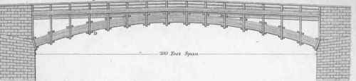
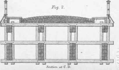
The vertical pieces which support the roadway are intended to be fixed in pairs, notched on to the ribs and bolted together. At each pair of upright pieces a double tie is intended to cross both the back and under-side of the ribs, to which they should be notched; they should also be bolted to the vertical pieces.
Between the timbers which carry the joists of the roadway, diagonal braces should be framed to secure the bridge from lateral motion, where the bridge is subject to the passage over it of heavy loads moving at a considerable speed, as in the case of railway bridges. A series of braces, though not shown on the drawing, should also be framed over the back of the ribs.
The bridge shown by Plate XLVIII. is intended for a gravel or paved roadway, and is calculated to sustain two loaded waggons at its weakest point without injury.
354. For spans greater than 250 feet, instead of single curved ribs, two might be used, one placed above the other, so as to admit of the space between being filled in with a framing of vertical or radial pieces with diagonals between, as shown by Fig. 10, Plate XLVII.
Continue to:


My Books

