


Of King Posts (sometimes called Crown Posts). Part 2
Description
This section is from the book "Elementary Principles Carpentry", by Thomas Tredgold. Also available from Amazon: Elementary Principles Of Carpentry.
Of King Posts (sometimes called Crown Posts). Part 2
257. Tie-beams are often unnecessarily cut to pieces with mortises where the king or queen posts join them, it is much better to make the tenons to the lower end of these posts very short, and to support the beam by means of straps. The best method of cocking or cogging the tie-beam upon the wall plate is shown by Fig. 83.
Sometimes blocks are placed under the ends of tie-beams, for the purpose of adding to the security of the roof in case they should decay. The roof of the Basilica of St. Paul's (Plate XXVIII.) has blocks of this kind. Several modern roofs have also been done in this manner, but as these blocks are as liable to decay as the tie-beam itself they cannot be of much use. And by adding to the depth of timber at the points of support, the settlement from shrinkage will be increased. Also, whether the blocks be firmly connected to the tie-beam or not, by raising the middle part of the tie-beam above the real points of support, a lateral pressure equivalent to that of a cambered beam will be exerted against the walls.
Fig. 81
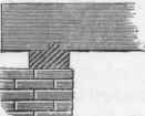
If the ends of the tie-beams be left with a perfectly free space round them, so that there would be nothing to retain any moisture in contact with them, there would be little to apprehend from decay. And if a further security should be thought necessary, cast-iron plates might be used instead of wooden blocks.
It is a common practice in framing roofs to force the tie-beam to a certain degree of camber, which appears to have been introduced under the idea that a cambered beam partakes of the nature of an arch; this, as has been justly observed by a late writer,* is one of the fallacies which it is the business of the mathematical theory of carpentry to dispel. It is obvious that when a cambered beam settles it has a tendency to thrust out the walls instead of being a bond to tie them together. The Gothic builders sometimes laid naturally crooked timbers with the round side upwards for tie-beams; but then their walls were capable of supporting a considerable lateral pressure. In some of the tie-beams of Durham Cathedral this curvature is very considerable; but modern walls are designed on different principles, and require all the assistance that can be given to them by the roof, instead of being sufficient of themselves to withstand the thrust of a cambered beam. Where there are ceiling joists it is easy to keep them a little higher in the middle of a ceiling, at the rate of about an inch in 20 feet, which prevents any settling that may take place, from offending " the eye of the beholder; " and consequently accomplishes all that Mr. Price and others propose to do by cambering the tie-beam.
258. When there is no ceiling nor floor in the roof to support, and the walls are not sufficiently thick to resist the thrust of the rafters, a wrought-iron tie-rod may be used instead of the wooden tie-beam.
* ' Encyclopaedia Britannica, art. Carpentry.
The thickness of the rod will depend on the design of the roof, and even in the same design, on the number of queen bolts and struts; but by finding the strains according to the principles given in Section I. of this work, and by allowing one square inch for every 5 tons of direct strain, the sectional area of the tie-rod can easily be found for any particular case.
Principal Rafters.
259. In estimating the strength of principal rafters, they are assumed to be supported by struts, either at or very near to all the points where the purlins rest. The pressure on a principal rafter is in the direction of its length, and is in proportion to the magnitude of the roof; but this pressure does not bear the same proportion to the weight when there is a king post, as when there are queen posts; therefore, the same constant number will not answer for both cases.
Case 1. - To find the scantling of the principal rafter when there is a king post in the middle.
Rule. - Multiply the square of the length of the rafter in feet, by the span in feet; and divide the product by the cube of the thickness in inches. For fir, multiply the quotient by .096, which will give the depth in inches.
260. Case 2. - To find the scantling of a principal rafter when there are two queen posts.
Rule. - Multiply the square of the length of the rafter in feet, by the span in feet; and divide the product by the cube of the thickness in inches. For fir, multiply the quotient by 0.155, which will give the depth in inches. *
The thickness is generally the same as the king or queen posts and tie-beam.
* For other forms of truss the stress on the rafters should be obtained by the graphic, or other methods, and the scantlings calculated as for pillars of wood.
Example. - The length of the principal rafter P, in Plate II. is 14 1/2 feet, and the span is 40 feet, the thickness of the truss 6 inches. The square of the length is 210.25, and the cube of the thickness 216. Therefore 210.25x40x0.155/216 = 216
6 inches nearly; that is, the principal rafters should be 6 inches by 6 inches
Straining Beams.
261. A straining beam is the horizontal piece between the heads of the queen posts, and is marked S in the roof (Plate II.).
In order that this beam may be of the best form for strength, its depth should be to its thickness as 10 is to 7.
Rule. - Multiply the square root of the span in feet, by the length of the straining beam in feet, and extract the square root of the product. Multiply this root by 0 . 9 for fir, which will give the depth in inches. To find the thickness multiply the depth by the decimal 0 7.
Struts and Braces.
262. The part of the roof supported by a strut or brace is easily ascertained from the design, but the effect of the load must depend on the position of the brace; when it is square from the back of the rafter, the strain upon it will be the least; and when it has the same inclination as the roof, the same strain will be thrown on the lower part of the principal rafter as borne by the strut. But as the degree of obliqueness does not vary much, no attempt will be made to include its effect in the rule for scantling.
Rule. - Multiply the square root of the length of the rafter supported in feet by the length of the brace or strut in feet;, and the square root of the product multiplied by 0 . 8 for fir will give the depth in inches; and the depth multiplied by the decimal 0.6 will give the breadth in inches.
Example. - In the roof (Plate II.) the part supported by the brace or strut B is equal to half the length of the principal rafter, or 7 feet; and the length of the brace is
6 feet. Therefore (7 1/2 x 6)1/2 x 0.8 = (2.646 x 6)1/2 x 0.8 = 3.985 x 0.8 = 3.188, the breadth; and 3.188 x 0.6 = 1.9128, the depth; or 3 1/4 by 2 nearly.
If a piece intended for a brace, a principal rafter, or a straining beam, be crooked, the round side should be placed upwards.
263. Rules have now been laid down for the principal parts of a truss, but in so doing no account has been taken of the weights of different kinds of roofing, nor the different degrees of inclination, lest the rules should become too complicated. For general reference the Tables of Scantlings at the end of the volume will be found useful, and with the assistance of a table of squares and cubes, or a table of logarithms, all the rules may be expeditiously worked out.
Continue to:


My Books

