


Of The Pressure On Curved Ribs
Description
This section is from the book "Elementary Principles Carpentry", by Thomas Tredgold. Also available from Amazon: Elementary Principles Of Carpentry.
Of The Pressure On Curved Ribs
174. Curved or arched ribs are adopted principally in the construction of bridges and roofs, where they are usually braced, so as not to depend too much on their own stiffness to resist cross strains. In order to determine what amount of bracing may be required, when it can be introduced, and to meet the cases where it cannot, as well as to determine the effect of any occasional force, as when a strong wind is straining a roof, or a heavy load passing over a bridge, it is necessary to consider first the case of a rib depending only on its own stiffness.
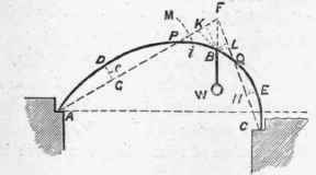
Let the irregular curve ABC (Fig. 46) represent the centre line of any rib, not necessarily of uniform strength throughout, resting on the immovable abutments at A and C, and supporting a weight W at B. The weight will tend to depress the rib and decrease its curvature at B, while it tends to raise it and increase the curvature at D, and probably also at E. Between B and D, and B and E, there will be some points, P and Q, where the curvature has no tendency to change, that is, where the thrusts or reactions which support the weight W pass through A and C and cut the curve. The reactionary forces at A and C and the weight W balance each other, and therefore their directions must necessarily meet in some point F in the vertical line B F. The forces which are in the directions A F and C F we shall represent by f and f'. The segments A D P, C E Q will act as bent struts, and the segment PBQ as a bent lever. The stresses on A D P and C E Q are due entirely to the stiffness of the lever P B Q. So one-half the sum of the moments of the forces acting on the arc A D P cannot exceed the sum of the moments acting on the arc P B, so also for the arcs C E Q, and B Q; the moments, however, may be very much less, which is the case on the side C E B, or they may completely disappear. In determining the position of P and Q take the position of P, so that one-half the sum of the moments of the force f acting on the arc A D B may equal the sum of the moments on the arc P B, and on completing the figure ascertain whether the moments of f' on B Q exceed half those on C B; if they do, the figure is correctly drawn; if they do not, it shows that the arc C E B should have been dealt with in the first instance, and then the moments on P B would have been found to exceed 1/2 those on A P. The forces ff can then be estimated by resolving the weight W in their directions. As the position of the weight W approaches C the point Q will also approach C, and under some conditions will coincide with it. The line F Q C may even fall outside the tangent to the arc at C, but it has been found in a variety of careful experiments on all sorts of curves, both regular and irregular, under every condition, that the equation of moments given above is strictly correct.
Fig. 46.
* By C. T. Guthrie, Esq.
There is one point where the weight may be placed which will cause on both sides 1/2 the sum of the moments on the haunch to equal the sum of the moments on the corresponding part of the crown. That point may be called the centre of equal moments. In a rib of irregular curvature it will generally be found nearer to one abutment than to the other. The maximum strain produced on a rib is when the weight is placed in such a position with regard to the centre of equal moments that the direction of the thrust on the abutment passes through it.
To estimate the sum of the moments of a force acting on an arc, multiply the length of the arc into its mean distance from the direction of the force. Its mean distance is the distance of its centre of gravity, supposing it to be a line of uniform weight. Thus, if the arc A P were the segment of a circle, the sum of the moments of the force f acting on it would equal 2/3 x ADP x D G x f, if its ver. sine does not exceed 1/4 of its length
Again, in calculating the sum of the moments on the arc P B we may find the centre of gravity of the arc by taking it at 1/3 the distance between the summit of the arc and the chord. The maximum strains on the arcs ADP, C E Q will be at D and E, the points most remote from the chords, and will be represented by f x D G and f' x E H. The maximum strain on the arc P B Q is at B, and will be represented by the moment fx BKorfxBL.
When a curved rib is exposed to the effects of a force acting at an angle it may be treated in the same manner as if acted upon by a weight, and when it is acted upon by two or more forces the effect of each may be considered separately, and then added or deducted, as the case may require. But when the weights or forces are very numerous, or when the weight is continuous, other methods of finding the strains should bo resorted to.
When the ends of a curved rib are rigidly secured in direction at the abutments, the lines of thrust no longer pass through them, but generally above, except the arc be the curve of equilibrium. The positions of P and Q are consequently altered, so that the moments on the arc cut off at A will equal 1/2 the moments on the remainder of the arc up to P, and will also equal the moments on P B. But the moments on the arc cut off at C cannot possibly exceed 1/2 the moments on the remainder of the arc up to Q. If the form of the curve admits it, the latter, however, will equal twice those between B and Q.
When a curved rib is exposed to strains which materially change the direction of the thrusts at A and B, the abutments should be arranged to prevent lateral motion at the ends.
When it is desired that there should be no thrust at the abutments, the rib should be calculated as a bent beam.
When a rib is built up of a number of pieces, in calculating its strength allowance should be made for the imperfection of the fastenings.
Continue to:


My Books

