


Cycles. Part 3
Description
This section is from the book "Workshop Receipts For Manufacturers And Scientific Amateurs. Supplement Aluminium To Wireless", by The Chemical Publishing Co.. Also available from Amazon: Workshop Receipts For Manufacturers And Scientific Amateurs.
Cycles. Part 3
The multispeed gear or hub for cycle use has been evolved for the purpose of allowing the rider to alter the gear ratio of the machine at will, and according to the work encountered. It must be simple to operate, give a useful range of gear ratios, and be proof against rough usage and bad weather. There are types of gear hubs which contain also a back pedalling brake, although the most popular type consists of a three-speed hub only. In general the devices cause the ratio of gearing between the chain wheel and the hub proper to be varied through the medium oi a fine-linked chain which passes into the centre of the hub axle at one end. When this chain is altered in position it causes an alteration in the gear arrangement to take place inside the hub. Springs control the return action of the chain into the hub axle when the necessary release of the chain is made. A further extension of the use of multispeed gears or cycles is the addition of a back-pedalling brake.

Fig. 56.

Fig. 56 shows a section of the 1920 three-speed hub made by Messrs. Sturmey Archer Gears, Ltd., and Fig. 57 gives the different parts of their K pattern three-speed hub, the parts follow one another in regular rotation, exactly as they should be fitted together. The different parts are as follows :-
N IR9 ;Step.
K 19 ;Left-hand cone.
X 25 ;Ball race cap.
X 24 ;|in. ball retainer.
K 17 ;Left-hand ball cup and pawls, etc.
N 66 ;Lubricator.
K 18 ;Hub shell.
K 46 ;Cage end cap spring.
K 45 ;Cage end cap
K 15 ;Planet cage.
K 16 ;Planet pinion.
K 5 ;Slirling clutch.
K 11 ;Gear ring.
K 13 Pawl pin.
K 12 ;Gear ring pawl.
K I ;Axle.
K 8 ;Right-hand ball ring.
X 2 ;Chain.
X 3 ;Screwed connection.
K 7 ;Driver.
X 24 ;Jin. ball retainer.
X 25 ;Ball race cap.
K 6 ;Right-hand cone.
N 222 ;Star washer.
K 9 ;Right-hand dust cap.
X 48 ;Sprocket.
N 200 ;Right-hand nut.
K 20 ;Chain protector.
X 6 ;Screwed connection lock-nut
Fig- ;58 shows the axle separately with gear pinion thereon.

Fig. 58.
Fig. 59 gives a section through the three-speed coaster hub, showing the brake arrangement operated by back pedalling. It will be readily seen that these hubs are well and compactly designed, but they are not articles to be gaily taken to pieces by any except those having some experience with mechanism and tools. All the bearings are adjusted simultaneously by adjusting the left-hand cone, while to take the hub apart, remove the left-hand cone, unscrew the right-hand ball ring (right-hand thread), thus detaching the entire gear from the hub shell.
Hand-operated brakes now nearly always act on the wheel rims, not the tyre or the wheel hub. They are either a suitable arrangement of levers and rods , or on the Bowden wire principle. The rod type by an arrangement of bell cranks and rods, cause brake pads to rub against the front or back wheel rims. Their actual method of operation may vary, but is always easy to understand by inspection; the points to watch and adjust are :
(1) ;see that the brake lever handle end is clear of the cycle handle bars when the brake is put hard on, if not adjust accordingly ; the particular method is easily discovered ;
(2) ;See that the brake pads are bearing on the wheel rims in the proper place, that is well towards the rim edges, and well away from the wheel spokes or tyre valve, etc. ; this is important, as if the pads catch and hold the wheel suddenly, an accident is nearly certain ;
(3) ;See that all joints are firmly secured, and yet free ; (4) See that the brake gear is not too flimsy, and liable to break on a sudden emergency ; and (5) See that it is not clogged with mud or liable to be so clogged.
The Bowden brake system works on the principle that if an inextensible steel wire or cable be placed inside a noncompressible flexible steel tubing, then within reasonable limits the arrangement can be bent round corners in a curve, and the flexible tubing being held firmly at both ends, the cable or wire being pulled at one end, will transmit the pull to the other end, quite freely and smoothly. The complete Bowden brake arrangement therefore consists of a lever device at one end, which carries a method of fixing firmly to the handlebar, and while holding the end of the flexible tube rigidly can pull the cable through the tube. The other end of the flexible tube is provided with means to hold it rigidly on to the machine at a convenient place near the actual brake device. This end of the steel cable is fixed on to the arrangement holding the brake blocks. It is now clear that if the brake lever is operated to pull the cable through the flexible tube then the brake blocks are pulled into contact with the wheel rim. A spring or springs are provided to pull the cable brake through the tubing so as to release the brake, as the Bowden system operates by a pull in one direction only. The cable should be well lubricated before placing through the tubing. The length of the flexible tubing can be shortened by cutting with a pair of pliers, that of the cable is shortened by unsoldering it from the nipple through which the end is passed, taking care that the stranded cable does not untwist, then pushing it through to the desired position cutting it to such a length that it stands out about 1/8 inch beyond the nipple end, spreading the end out well, soldering all firmly, and with a blob of solder making the splayed cable end into a firm blob of solder and cable. With proper care and attention a Bowden system brake will give every satisfaction, and is unique in the ease and readiness in which it can be fitted to any type of cycle or cycle frame for either back or front wheel. The Bowden Brake Company have many designs of brake levers and attachments to suit all possible variations required. In all rim brakes care should be taken to see that no oil or grease gets on the rims or brake blocks, and also it must be remembered that all hand-operated brakes have a rigid limit of operation, that is the hand lever end has only a certain limit of movement, which the average rider's hand span can allow it, and also the average pressure is that of the average rider's hand strength; this force and its movement cannot be increased at that end, and as the brake blocks must make a certain amount of movement to clear the rims, when in an off position, it follows that there is a definite limit to the pressure which can be put on to the brake blocks. This shows the need of good, clean blocks of a material having a high co-efficient of friction with no waste movement anywhere in the system. A brake system can be devised and applied to increase the pressure on the brake blocks above that applied | by the rider's hand on the brake | lever, but it cannot increase the power applied by the hand, it being understood that power in this case is the product of pressure and the distance through which it moves. Owing to friction the ' power applied by the hand is always greater than the power reaching the brake blocks, the difference may be small, but there always is a difference.
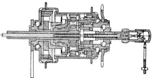
Fig. 59.
Continue to:


My Books

