


Hardness Testing Machines. Continued
Description
This section is from the book "Workshop Receipts For Manufacturers And Scientific Amateurs. Supplement Aluminium To Wireless", by The Chemical Publishing Co.. Also available from Amazon: Workshop Receipts For Manufacturers And Scientific Amateurs.
Hardness Testing Machines. Continued
For calibration, provision is made by means of the adjustable spigot .1. (see Fig. 81) for calibrating the load (a rare necessity) which should be 120 Kg., or 30 Kg., if ordered for use on very thin materials. By unscrewing the nut D the load cylinder may be withdrawn entirely from the machine body. The setting of the adjustable spigot is sealed before leaving the makers' works. For the purpose of checking the constancy of the load, a Standard Check Test Piece of known hardness is supplied with each machine for verification in case of doubt. A trip mechanism automatically arrests the motion of the hand-wheel as soon as the correct load has been applied. By reference to Fig. 81 it will be seen that when the load cylinder is forced down (carrying with it the trigger M) by means of the hand wheel and screw, the trigger M engages the recess in the inner bushing, which immediately allows the stop L to engage the rachet wheel K.
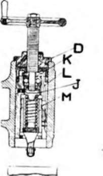
Fig. 81.
The Microscope
It will be observed that the eyepiece " B " of the microscope is built up of two tubular pieces-one slidable within the other. It is the relative positions of these two pieces which governs the focus of the scale. This eyepiece " B " (Fig. 82) is made an easy fit in the mircoscope tube, and the smaller or lower collar must make contact with the top of the microscope tube, or calibration will be interfered with. The microscope is fitted with a micrometer scale, which should firstly be focussed at " B" to suit the user's vision, so that the scale can be clearly read. Then, by means of the thumbscrew "C " the spot can be brought into focus, and the exact diameter of the impression determined by counting the number of divisions on the scale covering the impression (see Fig. 83). By reference to the correct table the corresponding hardness numeral is obtained. The correct microscope objectives " Y " should be used in conjunction with the load cylinder employed.
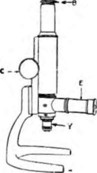
Fig. 82.
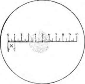
Fig. 83.
Beading The Impression
Type C2 Machine : The microscope should be placed over the object so that the pointer nearly touches the impression. An artificial light being fixed at the end of the side tube " E " so as to illuminate the field of vision thoroughly.
Owing to the possibility of irregularities of the surface being tested, it is advisable, where very great accuracy is required, to read the impression twice (by turning the eyepiece " B ")-one reading at right angles to the other, averaging any very slight variation that may be found. The impression of the diamond should be read diagonally, i.e., across the corners of the impression.
Measurements of hardness above 600 Brinell are not, in our opinion, reliable, on any machine in which a hardened steel ball is employed, as the ball itself is inclined to become temporarily or permanently flattened, and for this reason it is advisable to change the ball frequently. The frequency will vary with the hardness of the materials, but on materials averaging, say, 500 Brinell, it is advisable to change the ball daily if in constant use.
Continue to:


My Books

