


Projectors
Description
This section is from the book "Workshop Receipts For Manufacturers And Scientific Amateurs. Supplement Aluminium To Wireless", by The Chemical Publishing Co.. Also available from Amazon: Workshop Receipts For Manufacturers And Scientific Amateurs.
Projectors
These are now considerably advanced and improved, as compared with the old magic lantern. Fig. 174 shows one of the latest type, fitted for electric light, and with all improvements to satisfy working conditions and for greater convenience to travelling lecturers, demonstrators, etc., where district voltages vary. The resistance and half-watt lamp are adaptable to all voltages, and a 12 ft. picture at 60 ft. from the screen is possible.
A strikingly handsome outfit, mainly built in aluminium for lightness. Adapted with long bellows for using lenses up to 14ins. focus.
Specification. Body
Lamphouse, bulbous back, cowl, condenser cages, stages and lens front made in cast and polished aluminium. Extension tubes, tilting struts and clamping screws are heavily nickel-plated.
Condenser
Compound planoconvex, of special focus in new design of divided cage for easy access.
Carrier
Nickel - plated heavy brass.
Objective
Aldis - Butcher Projection lens, in black enamelled helical focussing mount, 8, 10, 12 or 14ins. focus; 8in. is supplied as standard.
Illuminant
27 volt. 5 ampere lamp with silvered reflector back.
Resistance
Calibrated for all voltages. Has metal cover, asbestos base and does not generate excessive heat.
Instructions For Use
After removing the Optiscope from case, place it on a stand or convenient resting place.
Remove the cowl and open the back door, then screw the lamp bulb into the screw socket, making sure that it is in good contact, and turn the fibre socket so that the filament of bulb is flat toward the condenser. Replace the cowl and shut the door.
Connect the resistance adapter to the supply circuit, seeing that the switch for same is " off," and also that the switch between cable is at " off " position.
Never put the plug into a live socket.
Place the lightning slide carrier in the Optiscope stage and insert a lantern slide in one side, allowing the empty side to remain in position in the stage.
Switch on both switches and extend the bellows by drawing it out after releasing the clamping screws until a clearly defined disc is shown on the screen, then clamp the screws. The lamp must be adjusted for height and perhaps a slight adjustment to one side or the other may be required in order to clear the disc on the screen from colour. When the current is switched on, the disc should be perfectly clear.
If the disc has a shadow on the right, the lamp must be moved to the left, and vice versa.
If the disc has a shadow on the top the light should be lowered, and vice versa.
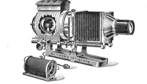
Fig. 174.
If the disc has a shadow all round its edge, then the light is too far away from the condenser.
If on the contrary a patch of shadow appears in the centre of the disc, while the edges are clear, then the light is too near to the condenser, and must be brought further away. If the picture requires raising on screen this can be done by means of the slotted runners and clamping screws at sides.
The carrier should now be pushed over so that the picture is thrown on the screen, and if not quite sharp it can be focussed by means of the rack and pinion adjustment of lens, or, in the case of the Aldis-Butcher Lens, by rotating the knurled edge which actuates the helical action backward and forward.
Care should be taken to see that all the optics are clean and free from dust: they should be cleaned when necessary with a soft chamois leather or Japanese tissue.
Great care must be taken of the bulb, as although the filaments are not very fragile, they certainly are delicate and liable to fracture from a sharp knock.
Continue to:


My Books

