


Telescope. A Home-Made 12 Reflecting Telescope. Continued
Description
This section is from the book "Workshop Receipts For Manufacturers And Scientific Amateurs. Supplement Aluminium To Wireless", by The Chemical Publishing Co.. Also available from Amazon: Workshop Receipts For Manufacturers And Scientific Amateurs.
Telescope. A Home-Made 12 Reflecting Telescope. Continued
To test, the mirror was set on edge and a small lamp with a metal chimney placed in the centre of curvature, i.e., 20ft. away. A safety razor blade on a stand acted as a knife-edge. Lamp and knife-edge are placed on a stout board on top of a strong low table. The metal chimney of the lamp is pierced with a fine needle to form a pinhole or artificial star. Placing the knife-edge on a level with the pinhole, the whole apparatus is moved forwards or backwards until a sharp image of the pinhole is formed on the knife. Both lamp and knife are now in the centre of curvature of the mirror. Applying the eye just behind the knife-edge the mirror appears full of light, the knife-edge is then moved towards the pinhole. The shadows at commencement of polishing resemble B (Fig. 200). That indicated under-correction. Make sure the knife-edge is at centre of curvature. Now remove the blade and fix an eyepiece in its stead, so as to magnify the image of the pinhole. Slide lamp, knife and all, towards and away from the mirror, so as to examine the appearance inside, at, and outside focus. The 125/8in. mirror gave a sharp image at focus, and sharp expanded discs inside and outside. That showed it was nearly spherical and under-corrected. At conclusion of polish ing the shadows were reversed and resembled A (Fig. 200). The eyepiece test showed the image inside focus to have a bright centre surrounded by a fringe of light, while the outer image had a black centre and a sharp edge. This indicates over-correction, i.e., an hyperbola, but the over-correction was not great. The mirror, while in this state, gave magnificent definition on the sun. I never saw the solar spots more perfectly than with power 100 soon after sunrise one fine morning. The reason was that the heat lowered the correction and made it approach the parabola.

Fig. 199.
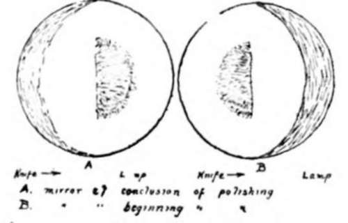
Fig. 200.

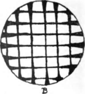
Fig. 201
The pitch tool was now cut in such a way that the central squares were reduced in size, and the marginal ones left full size (A, Fig. 201). If the figure had been under-corrected, the tool would have been dressed like B. I used a hacking knife and mallet. Two ten-minute spells on this brought the figure near the parabola. Examined with the eyepiece the image inside focus presented a slightly softer edge than the outside focus image. Owing to the great care taken, short strokes, continual rotation of the mirror with uniform movement, I saved both turned down edge and raised or depressed zones on the mirror. A disc of cardboard the size of the mirror was now cut, with a central hole 23/4in. dia., and two strips removed at the edge (Fig. 202). Place this on the mirror and adjust the knife edge so that when it is moved towards the lamp, both edge strips darken equally and at the same time. The central hole was not equally darkened, and I had to slide the knife edge towards the mirror before it darkened equally all over without revealing any moving shadow. The knife-edge had to be moved 7/6-in. towards the mirror to ensure this, this being a good correction. If the mirror was under-corrected, the knife-edge would have to be moved the opposite way. Use the formula v being the radius of the zone, and R the radius of curvature. My mirror had r = 51/2in. and R = 20ft., and was left with this correction, the solar focus was half the radius of curvature or 10ft.

Fig. 202.
A cell was made from a thick board and galvanised strip with cardboard round edge of mirror and small blocks to support the mirror, and also three to prevent it coming out. It is necessary to see that no strain is imposed on the mirror by the cell.
The tube, made from laths covered with ruberoid, is strong, light and weatherproof. The door for removal of the cell cover had a double layer of ruberoid to ensure dryness.
The flat was cut from a piece of plate selected as follows. Various pieces are laid on a table and the reflected image of the moon observed with a 3in. Refractor. A piece giving no distortion of the image was selected and cut into an ellipse 31/4in. by 21/2in. This was mounted in a metal cylinder (stout plate), and mounted on a stout arm fastened to the tube just below the round metal top.
If the instrument is mounted in a trunnion revolving in a cast iron pipe set at the correct angle in concrete, you will have a good equatorial stand.
Lastly, if one can induce (as the writer did) a friendly chemist to prepare the silvering solutions, a fine even film is more likely to be obtained, completing a really excellent instrument at a very low price. The total cost of the writer's telescope was under £2. (" English Mechanics.")
Continue to:


My Books

