


Marking And Guiding Tools
Description
This section is from the book "Manual Instruction: Woodwork. The English Sloyd", by S. Barter. Also available from Amazon: Manual Instruction: Woodwork.
Marking And Guiding Tools
The Marking Gauge is a tool or instrument used to make lines or scratches parallel to one side or edge of a piece of wood. Gauges vary in the details of their construction, but the pattern given in the illustration (fig. 35) is the best, and the one generally adopted in England.

Fig. 35.
The gauge consists of two pieces of wood, the stem and the stock, with a thumb-screw in the side of the latter, which, when tightened, holds the stock firmly in any desired position on the stem. The spur, or tooth, is a piece of steel pointed at one end, and which passes through the stem near the end of it. It will be seen that one side of the spur is sharpened flat and the other side rounded, as in fig. 36. The round side of the spur is the nearer to the stock when in use.
The reason of this is obvious. As the tool is used by pushing it away from the operator, while the tooth makes a cutting scratch on the surface of the wood, the shape of the tooth causes it to keep the stock well up to the edge of the wood. If the tooth were placed with the flat side towards the stock there would be a continual tendency in using to draw towards the edge of the wood, constant effort would have to be made to keep the stock pressed against the edge, with the result that irregular scratches, instead of a clean cut, would be made.
A good gauge may be known by the cleanness of the mortice through the stock, the straightness of the stem, and the quality of the boxwood screw. The beech stock and stem should make a good fit.

Fig. 36.
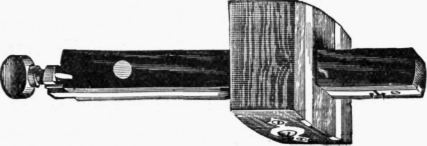
Fig. 37.
Mortice Gauge
(fig. 37). This tool is for marking two cut lines parallel to the edge of a piece of wood, usually to indicate the limits of a mortice or slot which is to be cut in the wood. It is similar in principle to the marking gauge, but two spurs or teeth are provided, and in order to obtain the power of regulating the distance of the two cut lines from each other, one tooth is fixed into the stem, while the other is bedded in a strip of brass which slides up and down the stem, obedient to the governing screw in the end. The points of the teeth are made to cut on both edges, and are rounded somewhat on both sides. There being two teeth, the liability to run out of the straight line is not very great.
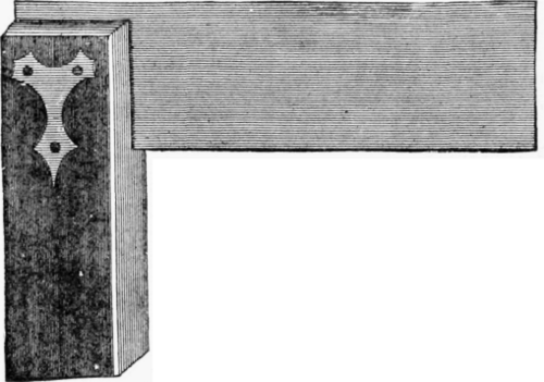
Fig. 38.
Try-Square
(fig. 38). So called because it is intended to test the accuracy of work; it is, in fact, used for a variety of purposes. The construction only of the tool will be described here. It consists of a thin blade of steel with parallel edges, fitted and riveted in, and at right angles to the stock. This is generally a piece of rosewood or ebony, shorter than the blade.
The stock of a good square generally has a piece of brass fitted on the inside edge to prevent, as far as possible, inaccuracies arising from wear. The rivets should be placed as in the illustration. Sometimes both blade and stock are made of wood, and when long-bladed squares are required, they are, of course, appreciably lighter than iron ones, though not so reliable. Squares are also made with steel blades, and cast or wrought iron stocks, but these are almost solely used by metal-workers.
The vital point in the construction of a square is the right angle between the stock and blade. To test the accuracy of this all-important angle, take a piece of wood with the face trued up, or planed level, and the edge perfectly straight.
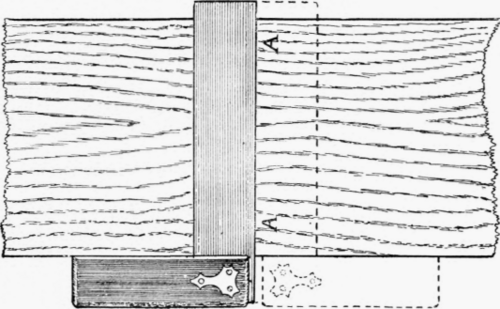
Fig. 39.
Place the stock of the square against the edge with the blade flat on the surface of the wood.
Mark a cut line along the edge of the blade a a, fig. 39. Reverse the square - i.e., place the other side of the blade against the line already cut, with the stock against the same side of the wood, and if the edge of the square coincides with the cut line, a a, then the square is true.
The reason is clear, for the angles contained by the cut line and the edge of the wood have just been demonstrated to be equal, and the second straight line falling upon the first straight line, and making equal angles with the edge of the wood, make the two angles right angles.
Should the square prove incorrect, the amount of the error is at once detected, and, if not too great, can be filed true. A great thing to look for in a square is the quality of the riveting, and this is of the utmost importance.
Squares vary greatly in size, which is always reckoned by the length in inches of the blade.
The Bevel
The Bevel (fig. 40) consists of a stock and blade held together by a screw pin.

Fig. 40.
The stock is made of some hard wood - rosewood or ebony-with brass mountings at each end.
The blade is made of a parallel plate of steel, with a slot to allow it to move up and down on the screw-pin at the end of the stock which passes through this slot.
The slot in the stock permits the blade to be pivoted completely round on the screw-pin, and, as it can be tightened in any position, any angle can be made between it and the stock.
In selecting this tool, be careful to see that the edges of the blade are straight and parallel, and that the screw of the stock, when tightened, grips the blade without bending it.
Compass
(fig. 41). The pattern in this illustration is the kind in common use. It is provided with a wing, which passes through a slot in the opposite leg when shut up.
The screw is useful to tighten up the legs at a particular set, as in marking curves on the surface of wood there would be a great liability for the drawing leg to open by being drawn from its course by the fibrous nature of the material.
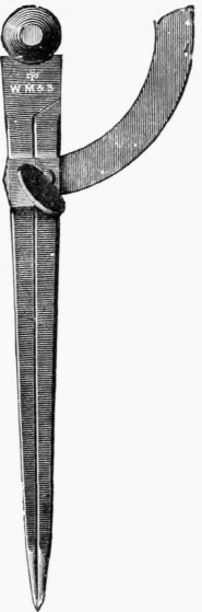
Fig. 41.
Continue to:


My Books

