


Cranked Tools
Description
This section is from the book "Workshop Receipts For Manufacturers And Scientific Amateurs. Supplement Aluminium To Wireless", by The Chemical Publishing Co.. Also available from Amazon: Workshop Receipts For Manufacturers And Scientific Amateurs.
Cranked Tools
The great advantage of cranked tools lies in their ease of grinding. Most grinding has to be done on the top face of the cutting tool, and with the cranked tool this is an easy matter. With the solid type of tool the corner of the grinding wheel has to be forced into the solid metal. For heavy cutting, however, the cranked tool is too springy, and the better type of tool is the upset tool (as shown in Fig. 98). This also permils of easy grinding on the top face, while still having great strength.
Roughing And Finishing Tools
The finish desired on the work is also a factor in deciding the design and cutting angles of tools. For steels a fairly high top rake should be given, especially for mild steel. The harder materials again must be finished bv tools that will endure the cut without undue wear, and hence their cutting edges cannot be too keen. The form taken by the cutting edge is of considerable importance. In roughing it is essential to keep the cutting portion of the tool edge as short as possible, because the power absorbed depends on the length of cutting edge in action. This has led to roughing tools with almost straight edges (see Fig. 98), especially for steel. A round nosed tool is very apt to cause chatter or vibration, on account of the long cutting edge and large amount of resistance; on the other hand, where cast-iron is being machined slowly on account of its hardness, the round nosed tool is more used, as chatter is much less likely at these low speeds.
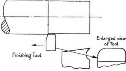
Fig. 100.
A point to be considered is the feed to be used. Thus, with a fine pointed tool, a very fine feed is necessary to get any sort of finish. With a radius on the tool point a coarser feed may be used, and thus for nearly all finishing a radius is used on the tool point. The larger the radius the coarser the feed that may be used, until a tool having a flat parallel to the direction of feed is produced. A tool of this nature, with the sharp corners slightly rounded with an oilstone, will produce a fine finish on steels even with a quite coarse feed. The feed, of course, must not be so great that a ridge is left (Fig. 100).
For the rapid finishing of cast iron a tool of the form shown in Fig. 101 is advised. This will take only a very light scraping cut of a few thousandths of an inch, but the feed used can be very coarse. Thus with a tool of one inch width of face, a feed of about three-eighths to half-an-inch could be used. Note that the cutting edge is behind the rear face of the shank of the tool, so that the springing of the tool will be away from the work. This principle is also made use of in the spring tools sometimes used for finishing steel, although this practice is now almost obsolete.
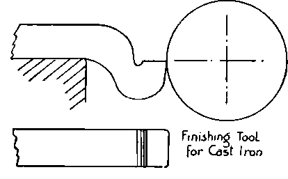
Fig. 101.
Setting Tools To Centre Height
>In turning it is essential that the tool should be correctly set in relation to the height of the lathe centre line. Although practice varies a little in this respect, it is better to set the tool point rather a shade below centre height than above, for this avoids any tendency to dig into the work if any extra pressure comes on the work. This point is illustrated in Fig. 102. It will be obvious that if the tool springs, it will move away from the work. If the tool is set above centre, any spring will result in the tool entering deeper into the work, with consequent spoilt work.
Provision must therefore be made for setting the height of tools correctly. The height may be taken either directly from the lathe centres if possible, or from a scribing block or other means. In setting the tools, always have as small an amount of overhang as possible, to reduce the possibility of the tool springing and chattering. In other words, support the tool as near as possible to the actual cutting edge.
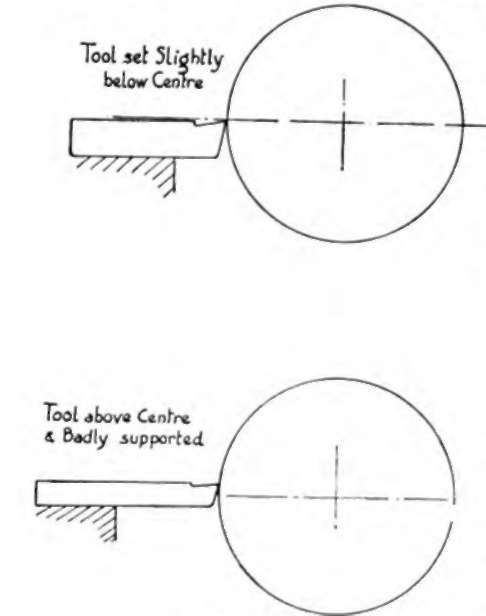
Fig. 102.
Various mot hods are employed for setting the tool to cenlre height, the ordinary method being to use packing pieces under the tool until the correct height is obtained. There are many designs of tool-holder, however, some of which enable the tool to be set to various heights.
The Toolholder described on page 145, see also Fig. 91, has several advantages for setting the tool to correct centre height. One of these is that the cutting angles remain constant for any height setting. This is not so with many holders, especially the " American " type holder, which consists of a tool post mounted on the topslide with an arc-shaped packing piece for the toolholder to rest upon. Raising the point of the tool in this type of holder means that the cutting angle is decreased, while the clearance is also decreased, with a danger of the tool rubbing.
Fig. 103 shows a set of slide rest tools of which the names are as follows :- 1, Outside Whitworth Thread Tool ; 2, Inside Whitworth 1 Thread Tool ; 3, Short Boring Tool ; 4, Long Boring Tool; 5, Narrow Parting Tool; 6, Left-hand Knife Tool ; 7, Right-hand Knife Tool ; 8, Square-edge Tool, or Broad Parting Tool ; 9, Left-hand Roughing Tool ;
10, ;Right-hand Roughing Tool ;
11, ;Front Roughing Tool ; 12, Round Nose Tool. Nos. 9 and 10 are Hook Tools, as shown in No. 11.
Chucks
These are one of the most useful accessories for any lathe; for the general run of work a three-jaw self-centreing type is the most popular, as if properly made and fitted the work is held firmly, and accurately centred with the use of one key only. It may sometimes happen that it is desired to hold a piece of work, etc., in such a way that it does not revolve about its geometrical centre, and then an independent jaw chuck is valuable, this being one in which each jaw can be moved quite independently of the others. The jaws in the above chucks are reversible as a rule, i.e., they can be taken out and reversed end for end, so that instead say of holding work on its outside, they can when reversed hold work, such as a ring, from its inside. Combination chucks have the advantages of all of the above, as they are reversible, are self-centreing, and in addition the jaws may be moved independently when required.
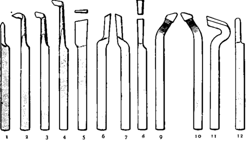
Fig. 103.
These Chucks are fitted with two keys, one for use in moving all the jaws together concentrically as in a Self-centreing Chuck, the other for moving each jaw separately as in the independent Chuck. Thus for holding irregular shaped work, the jaws can be separately adjusted to suit, and then operated in unison by means of the other key so as to automatically open and close to the same irregular setting for repetition. The jaws can be rapidly set true again for round work by means of the concentric lines on the face of the Chuck. Any shape of work can be held, as one or more jaws can be reversed, leaving the others as before. This method enables many awkward pieces to be held with facility.
Steadies
Where work of a long and slender nature has to be turned the need for steadies becomes apparent, and two have been designed specially to meet the requirements of the user of the Drum mond 31/2in. Centre Lathe.
The fixed steady is of the normal three point support type, and clamps to the bed by means of the plate at rear and the angle strip at the front. Three hardened set-screws support the work, the maximum size which can be admitted being 1 7/16ins.
The travelling steady is attached to the rear of the saddle by means of the two bolts shown, and its open form allows the cross-slide to operate without interference, in the usual way, besides giving additional stiffness to the design. The hardened Supporting piece is furnished with two vees as shown, and is readily adjusted by means of the set-screws.
The judicious use of a steady will be found to greatly increase the speed at which slender work may be machined, and will ensure a better finish and freedom from chatter. The fixed steady also provides a method of drilling, boring, and facing long pieces which may be held in the chuck, with their entire length overhanging therefrom and carried in the steady at their outer ends.
Continue to:


My Books

