40. Three-View Drawing
Description
This section is from the book "Elements Of Construction", by Charles A. King. Also available from Amazon: Elements of construction.
40. Three-View Drawing
Three-View Drawing. Any object to be drawn may be shown generally by three views; for instance, let us assume that the perspective sketch of the cross in Fig. 73 represents the idea, or the mental image, conceived in the mind of the draftsman, and of which he wishes to make a drawing as a means to the end of having the cross built.

Fig. 73. - Perspective View of a Cross, Illustrating the Three Planes of Projection Commonly Used.
In his mind he takes a position directly in front of the cross, and imagines that every part of its face is at exactly right angles with a line from his eye. This eliminates perspective, and he proceeds to draw the sketch shown in the front view of Fig. 74.
In doing this, he imagines a transparent plane between his eye and the mental image of the cross, at right angles with the line of vision, which we will represent by the plane abcd of Fig. 73. Using his paper as that plane, he draws upon it the lines, which, in his mind's eye, he sees projected there from the cross, as illustrated in the front view of Fig. 74. This completes the front view, and he must perform the same operation for the top view, imagining himself above the cross and looking directly down upon it, using the transparent plane c d e f, as his basis. The resulting lines are shown upon the top view of Fig. 74. The same method is followed in drawing the right side view of Fig. 73, working to plane bdfg. This same process could be continued around the six sides of the transparent box inclosing the cross, but these, as well as the drawings showing the sections of the object, are necessary only when three views will not describe the object sufficiently. The elevations and floor plans of a house, and its sections, are an instance where more than three views are essential.

Fig. 74. - Working Drawing of Cross, Illustrating Method of Showing Three Views upon One Plane.
Frequently two views will adequately convey the draftsman's ideas, as in Fig. 75.
Figure 76 shows three views of a table, upon which every necessary dimension is indicated.
Dimensions extend from arrow point to arrow point. The corner of the table top is cut away to show the detail of the connection between the leg and the rails. The dotted lines, representing the top view of the rails and the legs, illustrate one method of indicating construction.
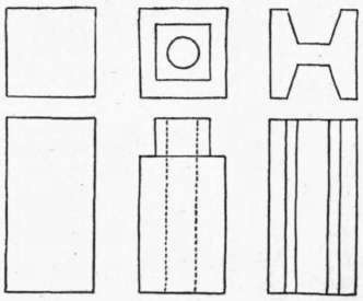
Fig. 75. - Two-view Working Drawing.
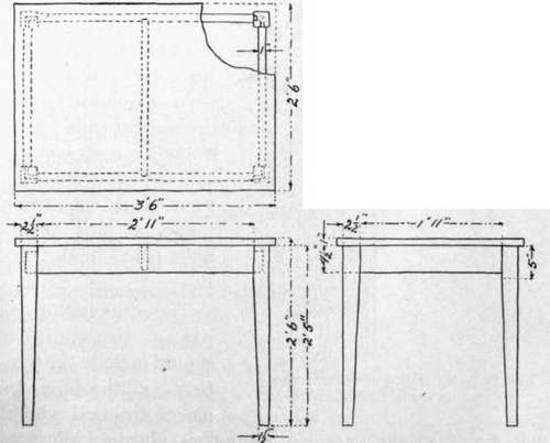
Fig. 76. - Three Views of a Table. - Methods of Indicating Construction : Dimensioning.
Continue to:
My Books

