13. Planes
Description
This section is from the book "Elements Of Construction", by Charles A. King. Also available from Amazon: Elements of construction.
13. Planes
Planes. (A.) The plane is the most complex, as well as one of the most important, tools which the woodworker uses, and a high grade of skill is necessary to keep it in order, as well as to use it properly.
(B.) The only plane in use until recent years had a wooden stock, and the iron was adjusted by blows with a hammer; this form of plane has changed very little since the first types were invented, as planes of ancient times have been found which in all essentials are practically the same as those in use to-day.
(C.) Our modern planes are more easily adjusted and more convenient to use, though they will do no better work than the wooden planes of our forefathers, which are still preferred by many of the best workmen. The face of an iron plane holds its shape permanently, while it is necessary that the wooden plane should be jointed occasionally.
(D.) There are planes for every conceivable purpose, all constructed upon the same general principle as the common bench plane which we shall discuss later. These planes are adjusted by screws and levers, which are very simple, and any one understanding them may easily comprehend the more intricate molding, or universal, planes. The adjustment of the modern plane may be understood by a careful study of Fig. 22 and by comparing it with the plane itself. The "cutter," "iron," or "bit" (1) and the "cap iron" (2) are the essentials of the tool, and it is upon their condition and adjustment that the efficiency of the plane depends. If the cap iron is set too far from the edge of the iron, and if the cut is made against the grain, the shaving will not break before it leads the iron into the wood, as shown in Fig. 23. If the cap iron is set somewhat less than 1 1/6" from the edge of the cutter, according to the wood being planed, it will break the shaving nearly as soon as it is cut, as in Fig. 24, and will result in a smooth, clean surface. The closer the cap iron is set to the edge, the smoother the iron will cut, as the breaks in the shaving are thereby made shorter.
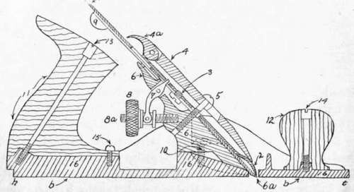
Fig. 22. - Section of Iron Plane.
1, cutter, iron, or bit; 2, cap iron; 3, plane iron screw; 4, cap lever; 4 a, cam; 5, cap screw; 6, frog; 6a, mouth; 7, Y lever; 8, vertical adjusting nut; 8a, vertical adjusting screw; 9, lateral adjustment; 10, frog screws; 11, handle; 12, knob; 13, handle bolt and nut; 14, bolt knob and nut; 15, handle screw; 16, bottom, or stock.
It will be seen also that the closer the bottom of the cap iron (2) is set to the edge of the cutter (1), the shorter the breaks will be, as in Fig. 24, and the more smoothly the plane will cut. The plane "iron screw " (3) holds the edge of the cutter (1) and the bottom of the cap iron (2) in their desired relation. The "cap lever" (4), being pressed against the under side of the head of the "cap screw" (5) by the "cam" (4 a), holds the iron in its place, and presses the cap iron (2) firmly against the top of the cutter (1). Unless the cap iron fits the face of the cutter perfectly, the plane will not work satisfactorily. The "frog" (6) carries all the adjusting mechanism of the plane, and may be moved backward or forward to reduce or enlarge the "mouth" (6 a), which should be no larger than is necessary to allow the shavings to pass freely. The frog rarely will require readjusting after it has been properly located.
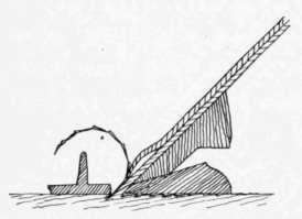
Fig. 23. - Result of Using Plane with Improperly Adjusted Cap Iron.
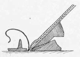
Fig. 24. - Result of, Using Plane with Cap Iron Adjusted Properly.
The "Y lever" (7) forces the plane irons (1 and 2) in or out simultaneously, which governs the projection, or "set," of the edge of the cutter (1) beyond the face, or "sole" (b), of the "plane stock," and thus the thickness of the shaving which the plane will cut. The " adjusting nut " (8) moves freely upon the "screw " (8 a) and operates the Y lever (7). The "lateral adjustment" (9) is for the purpose of forcing the iron to cut in the exact center of the width of the face (b) of the plane. The two "frog screws" (10) hold the frog rigidly in the position which will make the throat (6 a) of the desired size.
The above illustrates all the adjusting mechanism; the other parts of the plane are as follows: " handle " (11); "knob " (12); "handle bolt" and "nut" (13); "knob bolt" and "nut" (14); "handle screw" (15); "bottom," or "stock" (16).
The face, or sole, of the plane (6) must be perfectly straight, or good work cannot be done. The ends of the plane (h and t) are called the "heel" and "toe," respectively. The "mouth" of the plane (between 6 a and 2) must be kept clear of shavings, or it may become clogged.
(E.) In setting a plane, do not pass the fingers over the face, or sole, as cut fingers may result. Hold the plane as shown in Fig. 25, and look toward the light, when the exact projection of the cutter may be seen. Notice the position of the fingers of the left hand, and that the eye glances from toe to heel. This leaves the right hand free to make the adjustments. This is a workmanlike way of setting a plane, and in this, as in all handling of tools, awkwardness should be avoided.
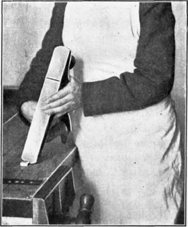
Fig. 25. - Setting a Plane.
Continue to:
My Books

