


Drawing. Part 2
Description
This section is from the book "Manual Instruction: Woodwork. The English Sloyd", by S. Barter. Also available from Amazon: Manual Instruction: Woodwork.
Drawing. Part 2
The method of dividing the line which is recommended is the usual workshop plan, and is quite as correct as, and much readier than, any other.
Draw a straight line a b on any convenient part of the paper, usually near the bottom, and from one end mark off 1/2 inch to equal 1 foot.
From e mark off 6 inches, b on AB = the sum of twelve 1/2 inches or 12 feet.
From a and e draw lines c d at any angles to the base line a b.
Along these lines mark off at any reasonable equal distances the number of divisions required, 12 on a c and 6 on e d. Join f e, and with the set-square, in the manner already described, draw lines parallel to fe from each point on a f and cutting a b; now a e is divided into 12 equal parts.
Join g b, and again draw from each point on e g parallel lines into ab.
The line being divided, finish and number the scale as shown in Fig. 3.
It will be noticed that the portion ae divided into 12 parts is in a manner additional to the scale, which, without it, represents 6 feet.
The value of this extra scale of inches will soon be appreciated in working from the scale, for if it should be necessary to mark off, say, 2 ft. 9 ins. or 4 ft. 8 ins., one point of the dividers can be at once placed on the unit of measurement required, and the distance obtained by stretching the other point out beyond zero to the number of inches required.
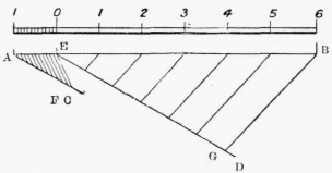
Fig. 3.
Orthographic projection, or right line drawing, is the system used for obtaining plans, elevations, and sections.
In all solid figures at least three dimensions exist - length, breadth, and thickness; and for the sake of clearness these are shown separately in working drawings. The plan of any object gives the space taken up horizontally by the dimensions which are either parallel or inclined to the surface of the paper, but gives no impression of their height or of their distance above this horizontal plane.
If vertical parallel rays of light fall on any object the shadow, visible or imagined, will be the plan.
Parallel horizontal rays of light would of course project the elevation on a vertical surface, and on the assumption of the existence of these rays of light the drawing of projections may be based.
If a rectangular slab of wood (fig. 4) 9 ins. by 5 ins. by 3 ins. is placed in the right angle formed by the folding up of a sheet of paper along the line x y, both the plan and the elevation can be drawn by marking with a pencil along the edges of the figure at the line of contact with the paper a a a a, a' a' a' a' on the horizontal and vertical planes respectively. The plan gives the breadth and length of the wood, but does not show the thickness.
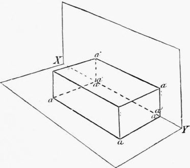
Fig. 4.
The elevation shows the thickness, or height, and length only. If the sheet is now smoothed out a complete working drawing is given. The plan, it will be seen, is drawn on the horizontal portion of the paper and the elevation on the vertical, but in actual drawings the folding of the paper is assumed, and the intersection of the vertical and horizontal portions is represented artificially by a line, x y.
It must not be imagined that only the part of the paper above x y is of necessity the vertical plane, and only that below is the horizontal plane. Planes are unlimited even surfaces 'in which any two points being taken a straight line joining them lies wholly in that plane,' and the paper only represents a limited portion of these planes. The surface of the paper is made to represent any plane, or any number of planes, as required. If planes are inclined to each other they must, being unlimited, pass through each other, and, where they cut, make a line of intersection called a 'trace' The horizontal and vertical, or co-ordinate, planes can be better understood by making a model with two sheets of paper, as shown in fig. 5.
Cut a notch in the sides of one piece and a slit in the other. Pass the notched piece through the slit as far as it will go, and unfold it. The two planes with their 'trace' will then be given.
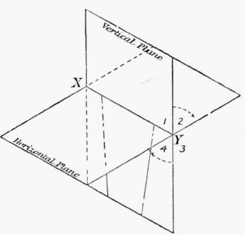
Fig. 5.
The arcs show the direction of the folding of the vertical plane into the horizontal plane, and the intersection, or trace, is the ground line, x y. The four dihedral angles of the co-ordinate planes are numbered 1 to 4.
No. 1 is in front of the vertical plane, and over the horizontal plane; No. 2 is behind the vertical plane, and over the horizontal plane.
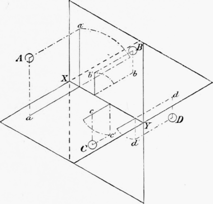
Fig. 6.
No. 3 is below the horizontal plane, and behind the vertical plane, and No. 4 is in front of the vertical plane, but under the horizontal plane.
Suppose a point a exists 1 in. above the horizontal plane, and 1 in. in front of the vertical plane, then the plan will be 1 in. in front of the trace, or x y, and the elevation 1 in. above. Fig. 6 shows the method of finding the plan and elevation on the folding planes, which, when the vertical plane is turned down to the horizontal, will give the drawing as in fig. 7.
Continue to:


My Books

