


Exercise XIII. Wedged Mortice And Tenon Joint
Description
This section is from the book "Manual Instruction: Woodwork. The English Sloyd", by S. Barter. Also available from Amazon: Manual Instruction: Woodwork.
Exercise XIII. Wedged Mortice And Tenon Joint
Fig. 207. The drawing should be plan and elevation, or isometric projection, but in the illustration other details are shown to enable the student to more readily understand the construction.
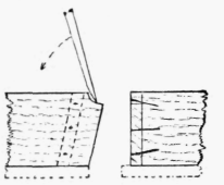
Fig. 206.
A piece of yellow deal 11 ins. long, 2 ins. wide, by 11/4 in. thick will be required.
Plane it up to the dimensions, and mark the usual line halfway from the ends.
Fig. 208 shows the setting out, and fig. 209 shows the wood prepared. In this case, however, the wood is turned round, showing reverse edge.
To set out, preparatory to commencing work, first mark the width of the mortice 1 3/4 in. on the face edge. From the end of these square lines, across the face side, and continue them across the reverse edge. On this back edge make two lines each 1/4 in. farther out, to give the space for the wedges.
At the end of the other half of the wood make a cut line on all four faces, for the shoulders of the tenon. This should be a little longer than the depth of the mortice, so that when put together the end will show through. The mortice and the tenon should be exactly the same size, and the mortice-gauge is used to ensure this. Take a chisel of the same width as the thickness of the tenon, and use this to test the setting of the mortice-gauge.
As a general rule the tenon should be one-third the thickness of the wood, but chisels, nominally of the same dimensions, frequently vary slightly, and it is desirable to use one which will be the exact width of the mortice. The mortice and tenon are, therefore, made to the same size as a chisel, which is practically, though perhaps not exactly, one-third the width of the wood.

Fig. 207.
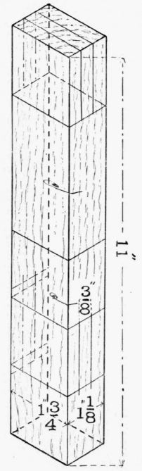
Fig. 208.

Fig. 209.
Having marked the dimensions of the mortice from the face side, using the tool in the same manner as the marking-gauge, the tenon should be marked on the end, and both edges, without altering the adjustment of the gauge. Take the mortice chisel and carefully place the edge at right angles to grain, near the middle of the wood to be removed, on the back edge, to make the mortice, and, holding it upright, give the end of the handle a good square blow with a mallet. Fig. 210 shows the method of using the mortice chisel.

Fig. 210.
It will be noticed that the face of the chisel is towards the operator. After making one cut (not too deep) take out the chisel, and proceed towards one end by a series of parallel cuts about 1/4 in. apart, prising out the waste, or core, with the chisel, by simply pulling or pushing the handle over after every cut. The chisel should be turned round after every few strokes, but the last stroke given should be with the flat face of the chisel towards the end of the mortice, in order that a true clean surface may be left.

Fig. 211.
As the mortising goes on, the cuts should be made deeper. The ends of the mortise from this side should be made to slope inwards, as shown in fig. 211, to give room for the wedges. After mortising out rather more than half the depth, turn over the wood and finish from the face edge, making upright ends to the mortice from this side. Cut out the tenon, sawing just to the gauge line, but be careful not to saw inside it, and then cut the wood in halves in order to join the two pieces. The two pieces of the joint, if successfully made, ought to go together without much pressure being necessary, and, on the other hand, they should not be loose.
Fig. 212 shows the shape of the wedges. They should be driven in with swinging blows from a hammer. In doing this do not give short sharp blows, but rather let the face of the hammer dwell on the top of the wedge at each stroke, in order to prevent any possible tendency to jump out.
From fig. 207 it will be seen that when the wedges are inserted, the joint becomes dovetailed in shape, and the object of the wedges is to make this dovetail, which gives the joint its strength under pulling strains. The important fact which must be considered in making this joint is the subsequent shrinkage of either half. Now as the wedge is driven in, the greatest crushing strain it has to sustain is near the blunt point, but if the wedge had a sharp point, the greatest strain would be near the thick end.
Shrinkage in the mortised half would cause the joint to open most at the outer end; and if this is the point of greatest compression, as with the pointed wedge, the joint once opened will be very insecure; but if the outside of a joint made with a blunt wedge were to open somewhat, the inner, less affected end, would still keep tight. The blunt wedge will, moreover, compress the fibres of the tenon most at the point of greatest strain - the inner end of the wedge, and will thus cause the tenon itself to assume a very slightly dovetailed shape; but with a pointed wedge the greatest strain will occur at the outer end of the tenon, and its fibres will be crushed at that end somewhat, so that any pulling strain on the tenon from the other side would be more likely to cause the joint to come apart - in fact, destroying to some extent the very object which the introduction of the wedges is intended to attain. The wedge, as will be seen in fig. 212, should be made with nearly parallel sides, and with one corner of the point pared off. Another method of making the joint adopted by cabinetmakers, with whom strength of construction is not so great a consideration, is to insert the wedges - pointed ones - into two saw-cuts across the end of the tenon. These wedges have the effect of forcing out the fibres of the outer edges of the tenon till they fill the sloping portion of the mortice.

Fig. 212.
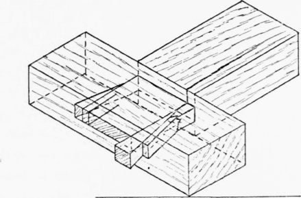
Fig. 213.
There are several objections to this method of making the joint, but the most serious is the breaking of the fibres of the tenon at the middle of the joint, where they are forced by the outward pressure of the wedges to assimilate themselves to the sloping sides of the top of the mortice. Fig. 213 shows this form of joint, with resulting broken fibres and split rail.

Front elevation.

Section on c d.

Section on a b.
Fig. 214.
Continue to:


My Books

