


Model II. - A Small Bracket
Description
This section is from the book "Manual Instruction: Woodwork. The English Sloyd", by S. Barter. Also available from Amazon: Manual Instruction: Woodwork.
Model II. - A Small Bracket
Fig. 128
This is an alternative and slightly easier model than the preceding.
A piece of yellow deal 14 1/2 ins. long, 5 1/4 ins. wide, 3/4 in. thick will be required. No change is necessary in tools used, except in the size of the centre bit, which should be 1/2 in.

Front elevation. Side elevation.
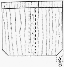
Plan.
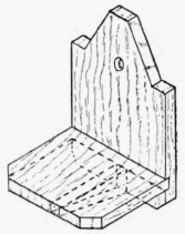
Fig. 128.
The drawings on the paper should be the usual orthographic projections, as in fig. 128.
The isometric projection is hardly necessary, as the very simple shape of the model is clearly brought out in plan and elevation, but it is given to make the drawing complete.
The wood should be first planed, and the development of the figure drawn on it, as in fig. 129. The lengths of the shelf and bracket and the limits of the grooves should be marked with square and chisel, and the remainder of the outline with a pencil. As much as possible of the work should be done before the several portions of the model are cut apart.
Commence by sawing off the waste at the end, then proceed to plane the end up true, having cut off one corner to prevent the breaking out of the end fibres. The groove for the shelf may now be made (to a gauge line 1/8 in. deep). Do not cut the shelf and back apart at this stage, as the whole piece should now be put into a vice and the bracket support and the sloping sides of the top sawn down along the dotted lines, as in fig. 129, with a hand saw.
The model should now be taken from the vice, and the shelf, the shoulders of the back, and the small triangular piece of waste at the top, cut off with the tenon saw. The shelf is complete, but the lower end of the back must be finished up in the same way as the end of the shelf, and the small groove, with the grain, for the back of the bracket support, should now be pared out.
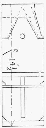
Fig. 129.
Notice the tick made to indicate the face side.
Fig. 130 shows the paring of the inner angle of the top of the back. This should be done in the vice, and the piece then taken out and laid flat, while the remainder of the waste left on from the saw is vertically pared off, as in fig. 131. The small flat top to the back should also be completed in this way. The bracket support should now be finished with plane and chisel, and before putting the parts together in their finished form, the hole in the back should be bored and the nail holes in both back and shelf made with a bradawl.
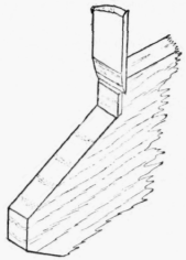
Fig. 130.

Fig. 131.
Similar nails to those for Model II. should be used.
Continue to:


My Books

