18. The Block Plane
Description
This section is from the book "Elements Of Construction", by Charles A. King. Also available from Amazon: Elements of construction.
18. The Block Plane
The Block Plane (A.) (knuckle joint cap, Fig. 32) is constructed upon a somewhat different principle than the planes above described, as the adjusting nut (a) under the cutter at the rear end of the plane is raised or lowered to withdraw or advance the bit, and thus govern the cut of the tool. The size of the mouth is controlled by a movable section of the face at b. This plane has no cap iron, as the use for which it is intended makes it unnecessary. The block plane is used across the end of the wood, at right angles with the general direction of the grain. The iron,. or cutter, is so placed in the stock of the plane that its cutting angle is as nearly in line with the cut as possible, the beveled side of the iron being uppermost. By this method of construction, the iron is given more stiffness to resist the chatter, or vibration, caused by planing end wood.
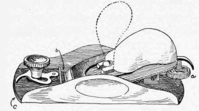
Fig. 32. - Knuckle Joint Block Plane. a, adjusting nut; b, movable section ; c, face of plane.

Fig. 33. - Use of the Block Plane. A, B, showing the block plane reversed.
(B.) In using the block plane, do not make the cuts from edge to edge, or chips will be broken off at the corners. Instead, plane from each edge, and stop the stroke before the other edge is reached; then reverse the plane, and work from the other direction, as shown at A, B, Fig. 33. Another workmanlike way of using the block plane upon small pieces is shown in Fig. 34. Work from each edge, as described above, turning the piece over for each stroke. In sharpening the block plane iron, the edge should be made slightly elliptical, and the bevel carefully maintained.
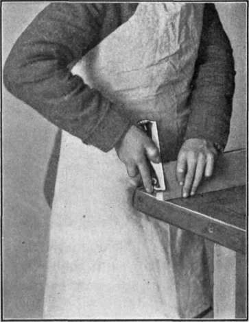
Fig. 34. - Using Block Plane upon Small Pieces.
Continue to:
My Books

