


Exercise IX. Lapped Halving Joint
Description
This section is from the book "Manual Instruction: Woodwork. The English Sloyd", by S. Barter. Also available from Amazon: Manual Instruction: Woodwork.
Exercise IX. Lapped Halving Joint
Fig. 180. This joint is really an outcome of Exercise I. The sketch in fig. 180 is all the drawing which will be necessary on paper.
A piece of wood 10 ins. long, 1 3/8 in. wide, and 1 in. thick will be required. This should be set out as in fig. 181, dividing it into halves by a line completely round the wood, and marking with cut lines two grooves on opposite sides to half the depth of the wood, and of the same width, as it is to be finished, 1 3/4 in.
The reason for marking these grooves on opposite sides is, that when the wood is cut apart and the joint put together the original face side will appear in both pieces on the same side. This might in actual work prove an important consideration, as the best possible surface may be wanted, and the face side has originally been selected on account of its superiority. The grooves should be sawn and pared out, as in fig. 182, and in shooting the edges of the wood afterwards, be very careful to make them perfectly at right angles to the faces, and on no account reduce the width to less than the breadth of the grooves, or there will be a loose, badly made joint when the two pieces are put together. When planed up correctly, cut the wood in halves, and make the joint.
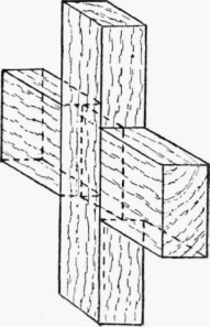
Fig. 180.
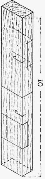
Fig. 181.

Fig. 182.
If really well made, the parts can be fitted tightly yet easily, and if taken apart, and one piece turned round, it should fit equally well. The depth of the grooves, too, should be equal, and exactly half the depth of the wood in a good joint, so that there is nothing to be 'cleaned off' when the joint is finished. There is no need to glue the joint, as it is not to be put to any practical use.
Continue to:


My Books

