


Model X. - An Oxford Picture Frame
Description
This section is from the book "Manual Instruction: Woodwork. The English Sloyd", by S. Barter. Also available from Amazon: Manual Instruction: Woodwork.
Model X. - An Oxford Picture Frame
Fig. 183
This model involves the fresh exercise of chisel modelling on the face of the frame, the mount should only be attempted in rare cases.
In drawing this model, the complete figure need not be attempted if the detailed drawings of the parts are made.
The dimensions of the frame are not given, as it may be wanted in any size, but it would be well not to attempt any thing-larger than 15 ins. by 10 ins.
Taking these measurements as a basis, 10 ins. by 7 ins. inside; two strips 3/4 in. by 1 1/4 in. and 15 ins. long, and two 12 ins. long, but otherwise of similar dimensions, will be required.
These four pieces of wood are planed up true to their proper size, set out, and half-lapped together. In order to ensure a true rectangular framing, they can be sawn in pairs. Two of the pieces can be cleated together, or screwed up in the vice with the two face edges together, and the grooves in each end marked and sawn out.
The other two strips should be similarly treated, but the grooves should be cut on the reverse side.
Gauge the rebate between the grooves from the face side on the inner edge of each strip 1/4 in. and on the back 3/16 in. away from the inner edge, as in the section on a b, fig. 183.
The rebate could be removed with the rebate plane, but it would take out the whole of the wood to the end of the 'horns,'
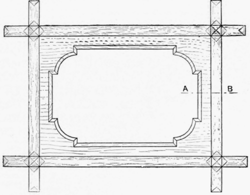

Elevation of Angle Of Frame
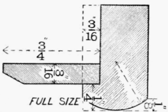
Section on A B

Plan or Angle as the small exterior processes of the frame are usually called. This is objectionable, and moreover it is not desirable to introduce the rebate plane yet. The removal of this rebate is effected with the chisel. First make cuts at right angles to the line gauged on the side, in the waste to be removed, and as deep as the rebate is required - 3/16 in. (see fig. 184). This has the effect of separating the waste into many small pieces, which may be forced out with the chisel, from the gauge line on the side. The small pieces of wood which may still require to be removed can be got out by horizontal and vertical paring. The waste at the ends of the horns should be cut off with a tenon saw, leaving a little to be pared vertically in order to obtain smooth ends. Joint up the frame dry, and smooth off both back and front true and level, and, after numbering each part, so that it may finally go into its right place, take the pieces apart. The round top of each strip should next be modelled. With thumb-gauge and pencil mark the depth of the curve on the edges, and draw a line down the middle of the face side, to show the top of the curve. It will be found of assistance to draw the line of curve on each end of the strips for guidance in working. This should be done with the jack plane in the first instance and finished off with glass-paper. Now put the framing together and with the chisel model the transverse curves at the ends of the horns and at the joints.

Isometric projection of angle of frame.
Fig. 183.
From Series IV. of ' Hand and Eye Training ' Cards, by kind permission of Messrs. Cassell & Co. Lim.
When the work is finished glue up the joints.

Fig. 184.
The mount should be made from a thin piece of wood of the proper side and planed true. Draw the shape on the face side and commence by boring out the curve at the corners. Complete the rest of the form by bow sawing and paring, and then chamfer with the chisel all round.
Continue to:


My Books

