Testing Plumber's Work. Continued
Description
This section is from the book "Sanitary Fittings And Plumbing", by G. Lister Sutcliffe. Also available from Amazon: Sanitary fittings and plumbing.
Testing Plumber's Work. Continued
4. The Hydraulic Test. - If a stoppage occurs near the foot of a waste-pipe or soil-pipe, it will probably not be discovered until the pipe has been filled (by discharges from the fittings) to the level of the lowest fitting, and the lower part of the pipe is thus subjected to a hydraulic test. Stoppages may be caused by accumulations of filth in the pipes or drains, or by ice, and it is obvious that the pipes ought to be sufficiently strong to withstand the pressure which may result from these stoppages. The water-test is useful for this purpose as well as for discovering leaks. In many cases this test is more easily applied than any of those already described. The end of a waste-pipe, for example, can easily be plugged with a cork, and the pipe can then be filled to the level of the lowest fitting. In the case of sinks, baths and lavatories with exposed standing wastes and overflows of the kinds recommended in the foregoing chapters, the outlets of the lower fittings can be similarly plugged, and the pipes filled to the level of the highest fittings. If the pipes are exposed (as they ought to be), the position of leaks will be easily discovered.
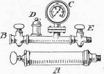
Fig. 212. Jensen's Pneumatic Apparatus for Testing Pipes.
Soil-pipes and ventilating-pipes are most conveniently tested before the connections are made with the drains; the lower ends must be plugged with drain stoppers. In the case of a ventilating-pipe the water must be inserted at the top. A soil-pipe can be filled to the level of the lowest fitting by discharges through that fitting. This fitting can then be plugged, and the next length filled from the next fitting, and so on to the highest. The uppermost length must be filled from the top. Cast-iron soil-pipes of any reasonable height are as a rule strong enough to withstand the test, but lofty stacks of lead pipe may be burst if they are tested as a whole. In such cases it is better to test the pipes in sections during the process of fixing, commencing at the top. If the uppermost length is proved tight, the next section can be fixed and tested, and so on to the foot.
The bursting strength of lead pipes is as a rule grossly overestimated. In one table it is stated that 1/2-inch pipes weighing 6 lbs. per yard may be used for a 500 ft. head of water; the writer has known many cases of fracture in 1/2-inch pipes weighing 9 lbs. per yard under a head of less than 400 ft. The following formula accords very closely with experiments made by Mr. D. Kirkaldy on lead pipes from § in. to 2 in. in diameter:-
t | = | hd | or | h | = | 5 st |
S | d ' |
where t | = | thickness of metal in inches, |
h | = | head of water in feet, |
d | = | internal diameter of pipe in inches, and |
s | = | safe tensile strain in lbs. per sq. in., or (say) 200 for lead, this being about one-tenth of the ultimate strength. |
From this formula the safe head of water for different sizes and weights of pipes has been calculated, the figures being given in the accompanying table. The factor of safety allowed is sufficient for waste-pipes and soil-pipes, as in testing these the pressure will be gradually applied, but a greater factor of safety ought to be allowed for service pipes in which severe shocks occur through the sudden closing of valves and taps.
Safe Head Of Water For Lead Waste-Pipes And In Inches. Soil-Pipes
Diam. | t = 1/10 in. | t = 1/9 in. | t =1/8 in. | t =1/7 in. | t =1/6 in. | t = 1/5 in. |
Feet. | Feet. | Feet. | Feet. | Feet. | Feet. | |
1 1/4 | 80 | 88.8 | 100 | 114.2 | 133.3 | 160 |
1 1/2 | 66.6 | 74 | 83.3 | 95.2 | 111.1 | 133.3 |
1 3/4 | 57.1 | 63.5 | 71.4 | 81.6 | 95.2 | 114.2 |
2 | 50 | 55.5 | 62.5 | 71.4 | 83.3 | 100 |
2 1/2 | 40 | 44.4 | 50 | 57.1 | 66.6 | 80 |
3 | 33.3 | 37 | 41.6 | 47.6 | 55.5 | 66.6 |
3 1/2 | 28.5 | 31.7 | 357 | 40.8 | 47.6 | 57.1 |
4 | 25 | 27.7 | 31.2 | 357 | 41.6 | 50 |
4 1/2 | 22.2 | 24.7 | 27.7 | 31.7 | 37 | 44.4 |
5 | 20 | 22.2 | 25 | 28.5 | 33.3 | 40 |
The weights per lineal yard of the pipes given in the foregoing table are as follows:in Inches.
Weight of Lead Pipes per Lineal Yard
Diam. | t= 1/10 in. | t=1/9 in. | t=1/8 in. | t=1/7 in. | t=1/6 in. | t=1/5 in. |
Lbs. | Lb?. | Lbs. | Lbs. | Lbs. | Lbs. | |
1 1/4 | 6.36 | 7.13 | 8.10 | 9.38 | 11.I3 | 13.67 |
1 1/2 | 7.54 | 8.43 | 9.57 | 11. 06 | 13.09 | 16.02 |
1 3/4 | 8.72 | 9.74 | 11.04 | 12.74 | 15.05 | 1838 |
2 | 9.90 | 11.05 | 12.52 | 14.43 | 17.02 | 20.74 |
2 1/2 | 12.25 | 13.67 | 15.46 | 17.79 | 2094 | 25.45 |
3 | 14.61 | 16.29 | 18.41 | 21.16 | 24.87 | 30.17 |
3 1/2 | 16.96 | 18.91 | 21.35 | 24.53 | 28.80 | 34.88 |
4 | 19.32 | 21.53 | 24.30 | 27.90 | 32.73 | 39 59 |
4 1/2 | 21.68 | 24.15 | 27.24 | 31.26 | 36.66 | 44.31 |
5 | 24.04 | 26.77 | 30.19 | 34.63 | 40.59 | 49.02 |
Weight of Met'l per sup. ft. | 5.93 | 6.59 | 7.41 | 8.47 | 9.88 | 11.86 |
It is clear from these tables that waste-pipes from 1 1/4 to 2 in. in diameter, and of the weights usually adopted in good work, are almost invariably strong enough to withstand the water test, even in the loftiest buildings. This cannot, however, be said of soil-pipes; thus, a 4-in. soil-pipe with metal weighing about 7 1/2 lbs. per sq. ft. ought not to be tested with a much greater head of water than 31 ft A 3 1/2-in. pipe with the same thickness of metal may be tested to 36 ft. with equal safety. The additional strength of the smaller soil-pipes is a point in their favour, which is clearly shown by these tables.
Continue to:
My Books

