Flush-Pipes
Description
This section is from the book "Sanitary Fittings And Plumbing", by G. Lister Sutcliffe. Also available from Amazon: Sanitary fittings and plumbing.
Flush-Pipes
The flush-pipes for trough-closets are of simple character and are generally supplied with the tank and trough. For latrines the pipes must be more complicated, as a branch must be taken to each basin. The pipes must be so arranged that every basin receives its proper share of the flush; this can best be effected by placing the tank above the middle of the range, and forking the main down-pipe so that it makes a double connection with the horizontal flush-pipe from which the branch flush-pipes are taken. A still more complete arrangement is shown in fig. 128, the main pipe being 3 in.
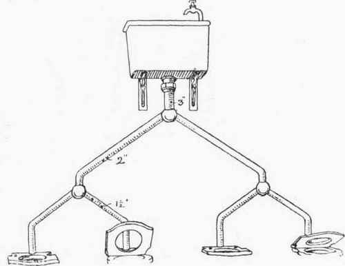
Fig. 128. Flush-tank and Pipes for a Range of Latrines.
in diameter, the primary branches 2 in., and the secondary branches to the basins 1 1/2 in. Frequently, however, the main down-pipe is connected to the horizontal pipe at right angles, and the latter is carried along the wall immediately behind the basins and a short branch is taken from it to each basin as shown in fig. 127. The horizontal pipe and the square junctions check to a considerable extent the force of the flush.
3. Waste-water Closets. Many water companies make an extra charge for ordinary water-closets, and as this charge was felt to be somewhat burdensome to the occupiers of small cottages, closets were designed for flushing with the waste water from sinks. The early closets of this kind were all objectionable on account of the great length of the tube (in some cases 4 ft. 6 in.) from the seat to the trap; this tube was soon fouled, and the closets became almost as evil-smelling as the pail-closets they were intended to supersede. Improvements of various kinds have, however, been effected in order to prevent or diminish this fouling, such as fixing the tube in a slightly-inclined position instead of exactly vertical, or making the lower portion of the tube of larger area than the pedestal, so that fouling would be confined to the latter, which, being nearer the seat, could be more easily cleaned from the top.
The essential part of all waste-water closets is the tipper for the reception of the waste water from the sink or yard gully. This tipper is swung on pivots, and is so designed that, when filled with water, it overbalances and discharges the water with considerable velocity, and, when empty, returns to its horizontal position. It is usually made of glazed stoneware, with a capacity of three gallons, rubber buffers being provided to prevent jarring and fracture. In some closets, as, for example, Day's "Stafford" closet (fig. 129), the tipper is placed directly below the seat, so that it receives the soil as well as the waste water. The tipper A is swung in the container B, which has a 6-in. outlet at the bottom, and fits into a trap C tapering from 6 in. to 4 in. The waste-water inlet is shown at D. Lengthening pipes are made for fixing between the top of the container and the pedestal in those places where the invert of the inlet is more than about 11 in. below the floor of the closet.
In courts and other places where two closets must be flushed from a single gully the first closet may be as in fig. 129, with the exception that a diminishing bend takes the place of the trap C. From this bend 4-in. drain-pipes are laid to the base-piece of the second closet, and the trap is fixed under this base. Plain tubes are carried up from the base to the pedestal. The water discharged by the tipper in the first closet passes, therefore, through the base of the second closet.
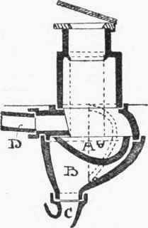
Fig. 129. Day's "Stafford" Waste-water Closet.
J. Duckett & Son's "Rapid" waste-water closet is a great improvement on the older types. The long tube between the trap and the pedestal is abolished by raising the tipper to a higher level. The general arrangement is shown in fig. 130. The pedestal is a wash-down closet and trap in one piece, but instead of the usual flushing rim, a channel is formed around the back of the basin; the pipe from the tipper is connected to this channel by a side inlet. Above the tipping chamber a channelled block 20 in. by 19 in. by 5 in. is fixed to receive the sink-waste and a 2-in. rain-water or other pipe. The top of this block is only 2 ft. 6 in. above the floor of the closet, so that this floor need be only-one or two steps below that of the scullery. This is certainly an excellent waste-water closet, and may be safely used in places where the ordinary kind would prove a nuisance.
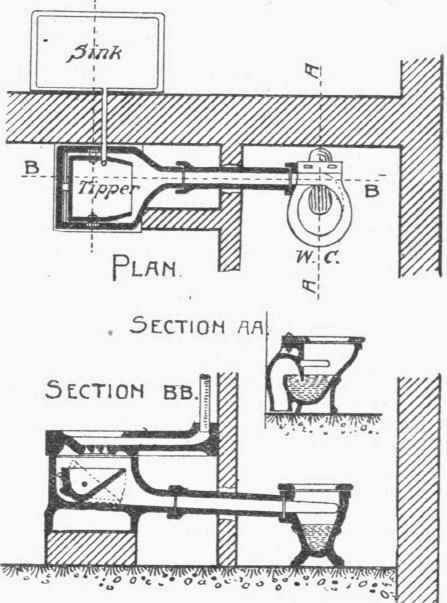
Fig. 130. Duckett's "Rapid" Waste-water Closet.
Experiments in several towns have shown that houses provided with waste-water closets require less water than those provided with ordinary water-closets, and this is an advantage not to be overlooked when the water-supply is limited. The sewage is also slightly less diluted, and this results in economy at the outfall works. Waste-water closets are also less liable to injury by frost. The Sanitary Inspector of Burnley reported in 1895 that, during the year ending March 25, 6.5 per cent. of the waste-water closets had been "noted as being out of order, and 37.4 per cent. of clean-water closets .... mainly on account of the frost."
The great disadvantage of ordinary waste-water closets is that the sides of the tubes are quickly fouled, with the result that the closets are more odorous than pleasant. All waste-water closets are objectionable because the soil is not removed immediately, but this objection is not so serious if there is a good depth of standing water to receive the soil.
Continue to:
My Books

