Chapter XV. Trough-Closets, Latrines, And Waste-Water Closets
Description
This section is from the book "Sanitary Fittings And Plumbing", by G. Lister Sutcliffe. Also available from Amazon: Sanitary fittings and plumbing.
Chapter XV. Trough-Closets, Latrines, And Waste-Water Closets
1. Trough-Closets
Trough-closets are a simple kind of water-closet, and have been extensively used in connection with factories, barracks, schools, and other buildings, where accommodation is required for a large number of persons, and where simplicity of construction, strength, and automatic action are desired.
In some early trough-closets a valve was placed in a small compartment at one end of the trough, and the contents were discharged by raising the valve. A small chamber was provided at the other end and fitted with a ball-tap to regulate the height of the standing water. In another example, a standing waste-and-overflow was fitted over the outlet-trap. The depth of water was regulated by the overflow, and the contents of the trough were discharged by raising the overflow tube from its seat. A great depth of water can be obtained by these means, but automatic arrangements are now generally preferred.
More modern trough-closets have a trough-generally of salt-glazed stoneware-with a weir at one end, so that a certain amount of water is always retained in the trough for the reception of the soil, and with a flush-pipe at the other end fed from a cistern usually automatic in action. Longitudinal and transverse sections of a simple type are given in fig. 122; the top of the trough is open from end to end, the seat being simply a continuous wood rail bolted to the front edge. A course of splayed bricks is shown along the back to prevent liquid or solid matter falling into the space behind the trough. As dirt from the floor of the closet is certain to be blown or swept into this space, it is a good plan to fill it with fine cement concrete after the trough has been tested; the angle above the top of the trough can then be finished with glazed bricks or with a triangular fillet of cement. The water from the flush-pipe is in this example discharged through a bent nozzle opening near the bottom of the trough-an arrangement which reduces the splashing and ensures a better flush than if the pipe discharges vertically into the standing water.
The troughs are generally made in lengths of about 2 ft., but in order to reduce the number of joints special troughs can be obtained up to 4 ft. 6 in. long. The troughs must be set perfectly level; if the outlet end is too high the soil will be difficult to flush out, and if it is too low, the depth of the standing water will be reduced towards the inlet end. The joints ought to be made with neat cement, and the troughs tested by filling them with water after plugging the outlet.
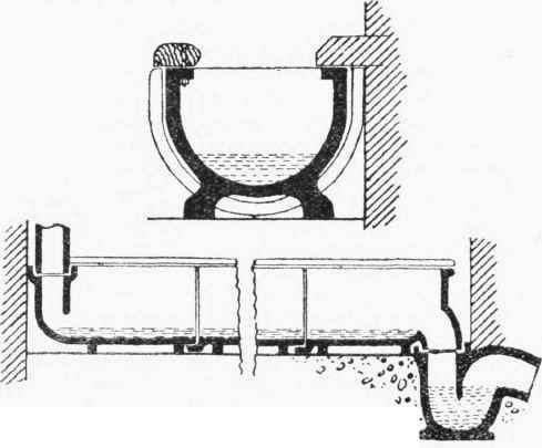
FIG. 122. Ordinary Type of Trough-Closet.
The points to be observed in trough-closets are (1) that the sides of the trough above the water level are so designed that they cannot be easily fouled, (2) that the depth of the standing water is sufficient to cover the soil, while at the same time the quantity of water is not unduly increased, and (3) that the shape of the trough is such that the contents are easily flushed out. Various sections are given in fig. 123; A is a simple arc, measuring about three-quarters of the circumference of the circle; B is a good shape, having the greatest depth of water towards the back of the trough; C is less satisfactory as the greatest depth is in the middle; D is a massive trough with flat base, which can be bedded in cement mortar on the floor of the room; E is peculiar in having a perforated flushing-rim along both sides.
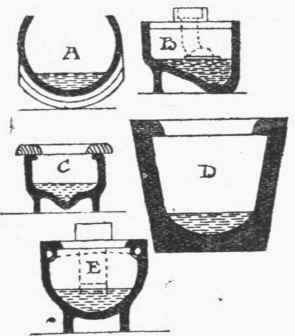
Fig. 123. Transverse Sections of various Trough-Closets.
Trough-closets are also made with a siphonic discharge. Duckett's apparatus is shown in fig. 124. The trough is of improved shape, and has a channel bolted along the back edge to serve as a flushing-rim and as a conduit for the water. The inlet A is 3 in. in diameter, and is supplied from an automatic siphon flush-tank. An air-pipe B is carried up from the top of the bend between the two outlettraps, and is so connected to the flush-tank that siphonage in the trap C is stopped before all the contents of the tank have been discharged; the last portion of the flush is therefore available for recharging the trough. The whole of the flush-water passes through the troughs, and the outlet-traps can, of course, be turned in any direction.
Instead of the continuous open top, trough-closets are often made with the top of each section partially covered, so that wood seats of ordinary form can be attached. In other cases the trough is replaced by a round or oval tube, with a junction at the top for the reception of the seat, as shown in fig. 125. The vertical portion ought to be specially designed to prevent fouling. The space behind such closets cannot possibly be kept clean, and ought therefore to be filled with fine concrete. Fig. 126 shows another modification, in which the only standing water is in the dished junction-piece under each basin. This water is too shallow to be of much use.
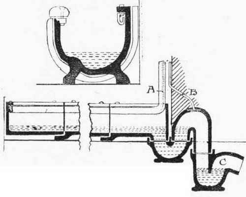
Fig. 124. Duckett's Siphonic Trough-Closet.
Trough-closets require a large volume of water. A discharge of fifty gallons is sometimes allowed for ranges up to 12 ft. in length, seventy gallons for ranges from 13 ft. to 17 ft. long, and 100 gallons for ranges from 18 ft. to 22 ft. long. These quantities give a minimum flush of about ten gallons per seat, but smaller quantities down to six or even four gallons per seat are often allowed, although of course the result is less satisfactory. The discharge of these large volumes of water causes a considerable amount of splashing, which is often very annoying. The flush-tank may be regulated to discharge automatically at stated intervals. No hard and fast rule can be laid down as to the number of flushes required daily, as so much depends upon the amount of usage which the closets receive; but it is always best to err on the side of cleanliness. Sometimes a "controlling vessel" is fitted to the trough and so arranged as to receive the overflow of water caused by the deposits. The filling of this vessel brings on a supply of water to the flush-tank (which has already been partially filled through a pipe controlled by a ball-tap), and starts the siphonic action. The frequency of the discharge is thus automatically regulated by the usage of the closets. An objection to such an apparatus is that the closets may remain unflushed for long periods, although containing a considerable amount of objectionable matter.
2. Latrines.- Trough-closets are far from satisfactory. The standing water is as a rule too shallow to cover a number of deposits, and emanations from one part pass through the whole range, thus increasing the risk of infection. It is much better to have a range of separate basins trapped from each other by the standing water. The name "latrines" may with advantage be confined to closets of this kind in order to distinguish them from trough-closets. They are emptied by siphonic action, which is started by the discharge from a flushing-tank, generally automatic, but sometimes operated by a pull.
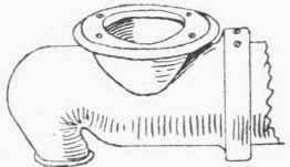
Fig. 125. Trough-Closet with Junction for Seat.
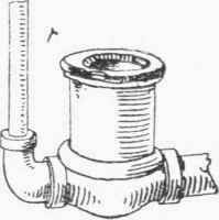
FIG. 126. Modified Trough-Closet.
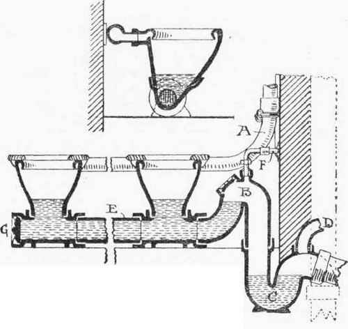
Fig. 127. Range of Siphonic Latrines.
Fig. 127 shows the longitudinal and transverse sections of a range of latrines of this kind. The basins are usually fixed 2 ft., 2 ft. 3 in., or 2 ft. 6 in., from centre to centre, but longer connecting pipes can be obtained if required. The flush-pipe A for ranges of not more than six closets is 2 1/2 in. in diameter with 1 1/4-in. branch to each basin. The basins are provided with flushing rims, and contain a considerable quantity of water, which is held up by the weir of the siphon at B. Below the long leg of the siphon a trap C is fixed, of P or S shape, fitted with a nozzle for an anti-siphonage D. The connecting pipes E and the siphon and trap are 4 in. in diameter. From the top of the siphon bend a 3/4-in. air-pipe F is carried up and either bent down into the cistern or connected with the flush-pipe, in such a manner that the siphonic discharge of the closets will cease at a certain point in the discharge of the flush-tank; the last portion of the flush is thus utilised for re-charging the closets. It is difficult to regulate this exactly, and the standing water is often considerably below the level of the weir at B. To obviate this, a small vessel with a separate supply-pipe controlled by a ball-valve may be advantageously fixed on the floor at one end of the range, and connected to the junction-pipe under the first basin. The ball-valve is arranged to shut off the supply when the water standing in the range approximates to the level of the weir at B. With high-piessure supplies secret waste may easily occur, and many water companies consequently object to the arrangement except in the case of buildings supplied by meter.
The connecting-pipes in fig. 127 are above the floor, which is a convenient position when the range is in an upper story, but the space behind the pipes cannot possibly be kept clean, and ought therefore to be filled with concrete. The stopper G facilitates access to the'connecting-pipes. In many cases longer hoppers are used and the connecting-pipes are laid below the floor.
It is obvious that when (as in fig. 127) the hoppers are fixed on the top of the pipes the contents of the first hopper are drawn under each successive hopper, and perfect isolation is not obtained. A slight improvement is effected by placing the siphon transversely in the middle of the range instead of at one end. A more recent form of Duckett's latrine has the pipes behind the hoppers, each hopper having an oblong outlet at the back, fitting into a corresponding socket in the side of the pipe. This ensures an almost perfect isolation.
Latrines are often fixed in well-ventilated outbuildings with thin walls, and are thus practically unprotected from frost. The result has been that in many cases the basins and connecting-pipes have been cracked in severe weather. It is, therefore, advisable to use fittings made of strong stoneware of considerable thickness, and also to adopt some arrangement whereby the water can be drawn from the range, the outlet-trap being, of course, left charged to prevent the passage of sewer air into the buildings. In Duckett's siphonic latrines a cock is fixed in the air-pipe connecting the siphon and tank; when this cock is closed and the flush-tank discharged, practically the whole of the water is siphoned out of the latrines.
Wash-down closets are often fixed in ranges to form latrines, and flushed by a single tank. The outlets of the closet-traps may be flanged and bolted to a cast-iron pipe above the floor, or may be connected by short branch pipes to a pipe laid below the floor. The closet shown in fig. 105 is well adapted for the purpose, having a flat back and a side outlet. The flush-tank should be large enough to give a flush of five or six gallons to each basin at each discharge.
Continue to:
My Books

