Trap-Ventilation
Description
This section is from the book "Sanitary Fittings And Plumbing", by G. Lister Sutcliffe. Also available from Amazon: Sanitary fittings and plumbing.
Trap-Ventilation
It is unnecessary to describe in detail, other conditions which lead to the unsealing of traps. The principal points to be borne in mind are the necessity of trap-ventilation (especially when the waste-pipes or soil-pipes are of great length or receive the discharges from two or more fittings), the importance of continuing the waste-pipes and soil-pipes (but particularly the latter) upwards to serve as ventilation-pipes, and the danger arising from trapping the lower parts of waste-pipes and soil-pipes.
The position of the antt-siphonage pipe requires some consideration. According to the by-laws of the London County Council, an anti-siphonage pipe should be connected with the branch-pipe at a point not less than 3 in., and not more than 12 in. from the highest part of the trap - of course, on the soil-pipe side of the standing water. If the anti-siphonage pipe is connected too near the highest part of the trap, the end will be fouled, and perhaps ultimately "furred up," by the discharges from the fitting rising into the pipe; if it is connected to the branch-pipe at too great a distance from the trap, it will be of little use in preventing siphonage.


Fig. 171. Tests of 3 1/2-in. Water-closet Traps (First Series).
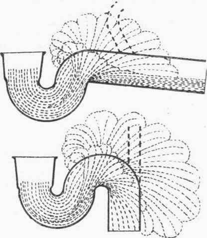
Fig. 172. Tests of 3 1/2-in. Water-closet Traps (Second Series).
The Committee of the Sanitary Institute already referred to carried out other experiments with the view of determining the best position for the anti-siphonage pipe.
Dubois traps of P and S shape, and 3 1/2 in. and 4 in. in diameter, were tested by fitting them to a short-hopper closet with 3 1/2-in. circular outlet, and by flushing the closet (1) with two gallons of water "thrown into the basin from a pail" and (2) with discharges from a 2-gallon siphon cistern fixed 4 ft. 9 in. above the top of the basin, and connected to it with a 1 1/4-in. lead flush-pipe. Glass tubes were fitted to the traps in various positions, so that the height to which the water rose could be observed. "Only one tube was fitted at a time, the other openings being carefully closed." Fig. 171 shows the results obtained with 3 1/2-in. traps, the P-trap having a seal of 2 1/8 in. and the S-trap a seal of 2 in. The shaded portions represent the maximum heights (out of six tests in each case) to which the water rose in the tubes, when the flush was thrown from a pail, and the black portions give the maximum results obtained when the closet was flushed from the cistern. These tests show that, for a closet used as a slop-hopper, the crown of the trap is not a suitable position for the anti-siphonage pipe. The further tests, illustrated diagrammatically in fig. 172 were made by cutting a slit 1 1/2 in. wide along the top of each trap, and observing the extent of the splashing. The outer dotted lines show the results when the closets were flushed from a pail, and the inner dotted lines those obtained when the cistern was used. It is clear from these illustrations that the anti-siphonage pipe will be seriously fouled if it is connected at right angles to any line tangential to the curve of the trap. The thick dotted lines in fig. 172 show how the anti siphonage pipes may be connected so that the risk of fouling is minimised.
In concluding this account of the Committee's experiments, it ought to be stated that the bare facts only are recorded in the "Journal" of the Sanitary Institute, and the Committee cannot therefore be held responsible for the deductions which the writer has drawn from these facts. A brief summary of an interesting series of experiments, carried out by Mr. S. S. Hellyer, will be given in Chapter XXII (Waste-Pipes From Urinals)., a greater variety of traps being used than in the tests just described.,
Continue to:
My Books

